R2 MTZ HI Instruction And Maintenance Manual Download Page 13


13 

13 

ENGLISH 

 
18. Make  sure  you  wear  close-fitting  clothing  that  cannot  easily  get  caught  in  the  implement's 

moving parts. 

19. Never put your hands into the hopper of the seeder unit (optional). Always close the cover of 

the hopper before using the implement and the seeder unit.  

20. In case the milling unit is jammed, do not work on it while the loader is on. First of all follow 

the routine described in point 1. 

21. Use particular caution when driving on steep roads, or when using the implement on trails or 

sloping ground.  

22. If  you  drive  on  the  road,  observe  the  traffic  regulations  in  effect  in  your  country.  Install  the 

required signal devices on the implement. Always check the maximum weight allowed on the 
wheel  axis.  Use  utmost  caution:  road  handling,  cornering  stability  and  braking  of  the  loader 
may  be  different  due  to  the  presence  and  position  of  the  implement.  During  the  transport, 
keep the implement in the lowest possible position and the nearest possible to the loader in 
order to keep low the gravity centre.   

23. The MILL GRADER mod. HI implement has been built for a precise work. It must always be 

in perfect working condition and should be repaired using only original R2 spare parts. 

24. Make  sure  all  persons  and  animals  are  clear  from  the  work  area  prior  to  powering  up  your 

implement or during use. 

25. For  any  intervention  on  the  implement  first  remove  it  from  the  loader.  Then,  place  the 

implement flat on the floor or on flat supports and in a stable position.   

26. All  fluids  under  pressure,  especially  the  hydraulic  fluid,  can  provide  serious  skin  lesions.  In 

this case consult immediately a doctor: risk of infection.   


Summary of Contents for MTZ HI

Page 1: ...ENGLISH Mill Grader Mod MTZ HI Instructions and maintenance manual Translation of the original instructions Rev 01 10 2014...

Page 2: ......

Page 3: ...ent 10 Accident prevention 12 Component assembling 14 Hitching the implement to the loader 18 Connecting and disconnecting the hydraulic hoses 20 Preparing for use 21 Adjusting the working depth 21 Ad...

Page 4: ...ance from the side and from the rear of the implement to prevent the risk of injuries and collision Always check that there are no people in range of the implement s movement and operation Anchor poin...

Page 5: ...ols used in this manual This symbol is used in this manual to indicate actions improper use of the implement elements behaviours and situations that can put your safety or the safety of other persons...

Page 6: ...SM seeder might be used in different ways and or for purposes other than those described in this manual the manufacturer declines any liability for damages to persons and or property of any kind Befo...

Page 7: ...7 7 ENGLISH Fig 2 A Roller assembly B Roller adjuster C Quick attach plate D Grader blade E Milling group F Side panel and side panel extension G Seeder assembly optional A B C E D F G...

Page 8: ...0 Weight in models with seeder total weight including the empty hopper given Kg 115 150 180 200 220 250 250 285 280 320 Seeder unit weight with empty hopper Kg 64 70 78 95 105 Hopper volume L 50 57 62...

Page 9: ...9 9 ENGLISH Fig 3a Fig 3b Fig 4a Fig 4b Fig 5 a b c B A C A A A D B...

Page 10: ...ble The anchor points may be the roller unit bracket the screw adjustment support and the front grader blade Fig 8 Make sure that the adjusting and fastening screws of the grader blade are well tighte...

Page 11: ...11 11 ENGLISH Fig 6 Fig 6a Fig 7 SM 135 150 170 Fig 7a SM 100 120 Fig 8 22...

Page 12: ...ns of the loader s quick attach plate are in the lower position and that they have locked the mill grader MTZ HI to the loader Never lift or transport the implement if it has not been locked 7 Never g...

Page 13: ...axis Use utmost caution road handling cornering stability and braking of the loader may be different due to the presence and position of the implement During the transport keep the implement in the lo...

Page 14: ...the mill and the screw register Fig 9 2 Assemble the seeder unit in place of the roller unit using the same attachment points Fig 10a Fig 11 Tighten the bolts so that the seeder bracket and the screw...

Page 15: ...15 15 ENGLISH Fig 9...

Page 16: ...16 16 ENGLISH Fig 10a Mod MTZ HI 135 150 170 Fig 10b A B...

Page 17: ...17 17 ENGLISH Fig 11 Mod MTZ HI 100 120 Fig 12...

Page 18: ...connections see paragraph 8 on page 20 Ensure that the hydraulic hoses are not in the way during installation STEP 2 Fig 14 Turn the quick attach plate hydraulically to an obliquely forward position D...

Page 19: ...19 19 ENGLISH Fig 13 STEP 1 300 700 series loaders 200 series loaders Fig 14 STEP 2 300 700 series loaders 200 series loaders Fig 15 STEP 3 300 700 series loaders 200 series loaders...

Page 20: ...of paragraph 5 on page 12 Use safety gloves and glasses NOTICE keep all couplings as clean as possible use the protective caps on both the attachment and the loader Dirt ice etc may make using the fit...

Page 21: ...of the side panel extensions in three different positions Fig 20 To avoid hoes protruding from the soil and therefore creating dangerous situations during the milling the side panels and the grader bl...

Page 22: ...22 22 ENGLISH Fig 18 Fig 19 Fig 20 Fig 21 Fig 22...

Page 23: ...ange the position of the knob on the graduated scale The quantity of seed to fall can vary depending on the mixture of seed used and the speed of the tractor In order to identify the optimal setting b...

Page 24: ...implement during operation Stay clear of moving mechanical parts Never leave your working place when the loader is on If during operation a lot of dust is stirred up which depends on the soil type we...

Page 25: ...earing chain of the roller brush motion of the hopper and finally reassemble the protective casing Control the chain tension the chain must fluctuate approximately 1 cm if necessary adjust the tension...

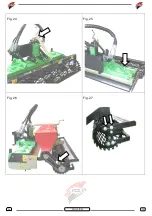
Page 26: ...26 26 ENGLISH Fig 24 Fig 25 Fig 26 Fig 27...

Page 27: ...area is dangerous Fig 29 During these operations position yourself firmly and securely and make sure that your face and your body will not be pressed against the hoes Do not allow people or animals t...

Page 28: ...t B Self locking steel nut M10 fine pitch DIN 982 C Nut seat D Hoe E Drilled plate F Reinforced Grower washer DIN 127 B G Steel screw M 10 x 1 25 x 45 fine pitch partial thread DIN 960 8 8 Tightening...

Page 29: ...place etc and protect the protruding parts so that they do not cause injury To avoid hazards store the implement in a way that it does not block escape routes emergency exits firefighting equipment ex...

Page 30: ...in this manual whenever the company deems it necessary for a technical or commercial improvement of the product The original text of the operation and maintenance manual has been written in Italian o...

Page 31: ...31 31...

Page 32: ...ed Office Via Valsellustra 25 29 40060 Toscanella di Dozza Dozza Bologna ITALY Head office Via degli Artigiani 23 40024 Castel San Pietro Terme Bologna ITALY Tel 0039 051 94 30 42 Fax 0039 051 69 42 0...

Reviews: