


Version 09.12.2020
HW: CAM(V100)/(V11+V41)
ab Serien Nr: NZ20NOV694
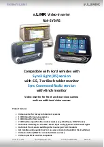
RL4-SY3-R5
P
a
g
e
6
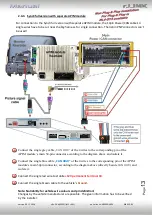
1.4.
Dip-switch settings
1.4.1.
8 dip - black
Some settings have to be selected by the dip-switches on the
video interface.
Dip position down is ON and position up is OFF.
*The front camera will automatically be switched for 10 seconds after disengaging the
reverse gear.
After each Dip-switch-change a power-reset of the Video Interface has to be performed!
See the following chapters for detailed information.
Dip
Function
ON (down)
OFF (up)
1
Front camera
enabled*
disabled
Power supply
output
(red wire)
+12V (max. 3A) when reverse gear
is engaged incl. 10 seconds delay
and +12V by manual switching to
front camera by keypad
+12V (max. 3A) ACC
2
CVBS AV1-input
enabled
disabled
3
CVBS AV2-input
enabled
disabled
4
PDC
enabled
disabled
5
Rear-view cam type
after-market
factory or none
6
Guide lines
enabled
disabled
7
Monitor selection
4inch monitor
6.5/7/8inch monitor
8
No function
set to OFF