background image

14

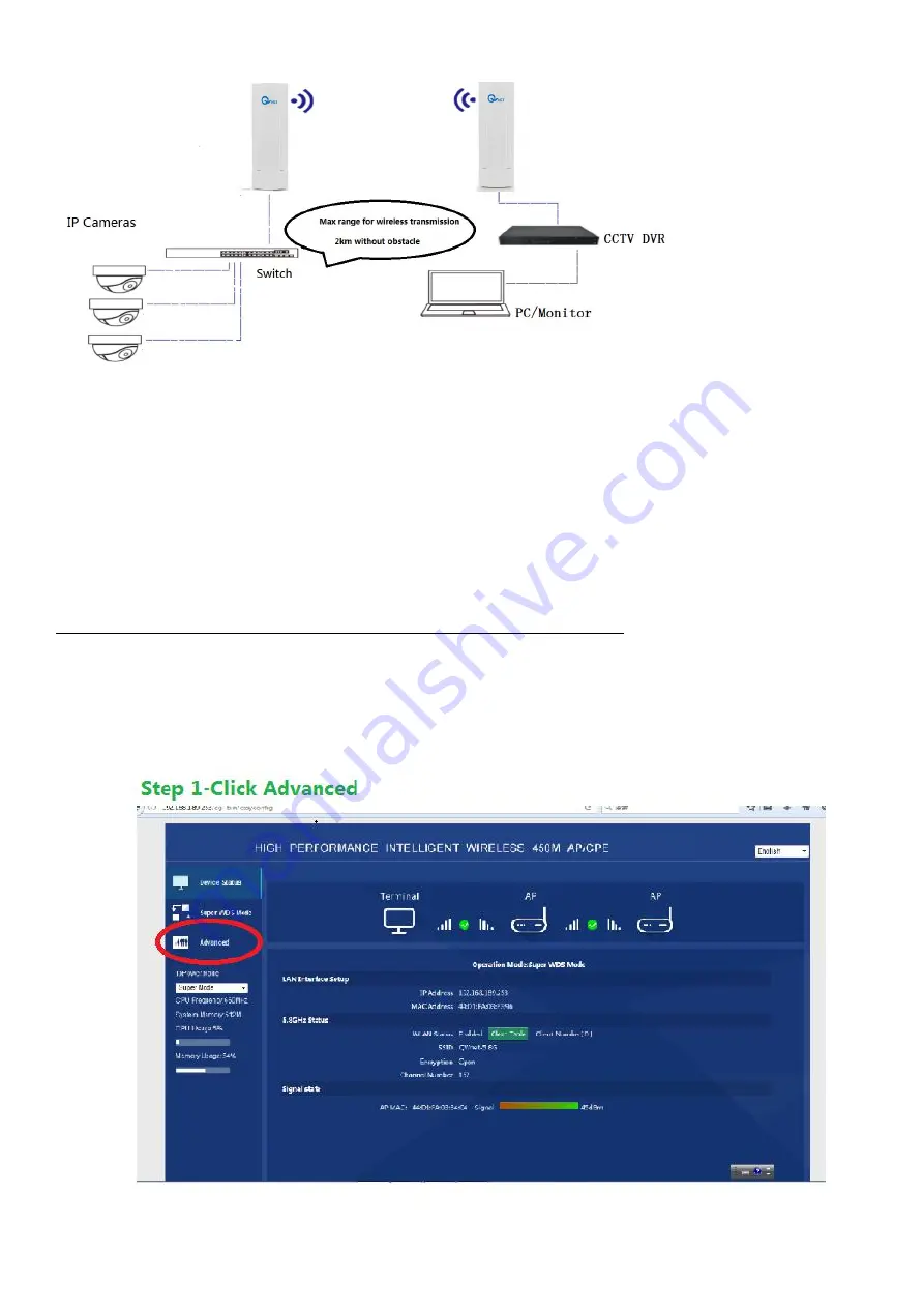
Sketch diagram

2-2-1 Use Ethernet cable to connect switch to IP cameras
2-2-2 Use Ethernet cable to connect switch to CPE5450 1#
2-2-3 Use Ethernet cable to connect LAN port of CPE5450 2# to POE port of power adapter
2-2-4 Use Ethernet cable to connect WAN port of CPE5450 2# to NVR/DVR
2-2-5 Turn on all equipment, wait for 1 minute, then you could see video of camera on monitor

2-3 With your router, to extend Wi-Fi signal, CPE5450 kit are used as Wi-Fi repeater

2-3-1 Please kindly refer to step 1-2-1 (from 1-2-1-1 to 1-2-1-7)
2-2-2 The default password for the device is : 66666666
2-2-3 IP address for another CPE, M (Master) CPE5450 is: 192.168.188.252,

and IP address for S(Slave) CPE5450 is :192.168.188.253, so you could log into the device via page to change
SSID and password of the device.

Summary of Contents for CPE5450 Slave

Page 1: ...1 CPE5450 Quick Start Guide Ver1 2 Jul 2017 Packing list 1 CPE5450 2pcs 2 POE Power Adapter 2pcs 3 Ethernet Cable 4pcs 2pcs for spare use 4 Metal Hoop with Screw Fastening 2pcs Product pictures...

Page 2: ...separately to check if the device is damaged from shipment if you can hear some noise from inside of the device and you suspect it maybe PCBA board loosened please contact us we will help check if you...

Page 3: ...or step 1 2 2 But you could neglect these 2 steps and proceed to step 2 1 if you don t have a Wi Fi router cabled router and you don t have computer PC or if you think you know CPE well 1 2 1 Sketch...

Page 4: ...connect POE port of power adapter to WAN port of CPE5450 2 1 2 1 4 Use Ethernet cable to connect LAN port of CPE5450 2 to PC 1 2 1 5 Set range between CPE5450 1 and CPE5450 2 3 meters is recommended...

Page 5: ...5450 are turning on wait for 1 minute Light is on Light is not on 1 2 1 7 Ping IP address of the Wi Fi router some is 192 168 1 1 or 192 168 0 1 on the PC You could find IP of router on label normally...

Page 6: ...ck Windows icon B Input command ping 192 168 1 1 t C Click enter to Ping 192 168 1 1 t Following messages indicates the CPE5450 devices are working well And you don t need to execute step 1 2 2 You co...

Page 7: ...or in M mode Master you could neglect this step and proceed to step 2 1 Sketch Diagram Equipment CPE5450 Slave in S mode 1pcs CPE5450 Master in M mode 1pcs PC Notebook 1 set POE Power Adapter 2pcs Eth...

Page 8: ...8 1 2 2 2 Connect CPE5450 Master to power adapter as following 1 2 2 3 Set range between CPE5450 Slave and CPE5450 Master 3 meters around 10 foot is recommended without obstacle between 2 CPEs...

Page 9: ...all equipment especially check as below to see if 2 CPE5450 are turning on wait for 1 minute Light is on Light is not on 1 2 2 5 Set IPv4 IP address or IPv6 IP address of the PC to 192 168 188 22 or 1...

Page 10: ...e PC Firefox IE browser are recommended To log into CPE Slave s page Enter User name admin Password admin If you can see Master s MAC address and signal strength like 46dBm as below it means the devic...

Page 11: ...2 1 With one camera Block Diagram Equipment CPE5450 1 pair 2PCS Camera 1pcs DVR NVR 1pcs Ethernet Cable 4pcs 2 1 1 Use Ethernet cable to connect WAN port of CPE5450 1 to IP camera 2 1 2 Use Ethernet...

Page 12: ...12 2 1 3 Use Ethernet cable to connect LAN port of CPE5450 2 to POE port of power adapter 2 1 4 Use Ethernet cable to connect WAN port of CPE5450 2 to NVR DVR...

Page 13: ...ll equipment especially check as below to see if 2 CPE5450 are turning on wait for 1 minute then you could see video of camera on monitor Light is on Light is not on 2 1 6 Installation tips 2 2 With m...

Page 14: ...Turn on all equipment wait for 1 minute then you could see video of camera on monitor 2 3 With your router to extend Wi Fi signal CPE5450 kit are used as Wi Fi repeater 2 3 1 Please kindly refer to st...

Page 15: ...n for longer than 15 seconds the devices will not maintain connection between 2 CPEs and then they need to be re configured If you push Reset button one time not longer than 5 seconds it may cause 3 m...

Page 16: ...16 3 Use metal hoop with screw fastening to fasten the device 3 1 3 2 3 3 3 4...

Reviews: