background image


© Copyright Qvis ®. All documentation rights reserved.   
 

46 

System  also  supports  the  upload  of  multiple  NVRs  to  one  FTP  server.  You  can  create  multiple 

folders under this FTP.   


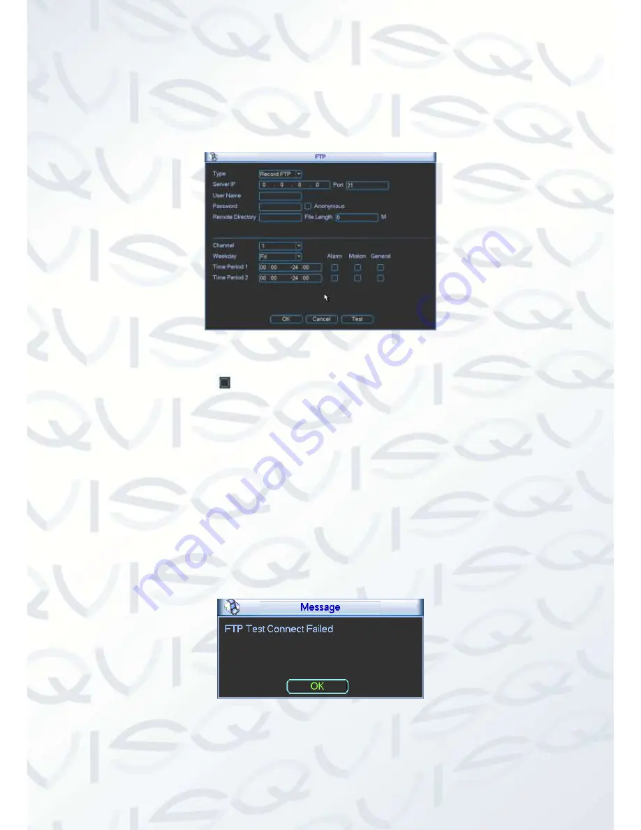
In Figure 4-31, select FTP and then double click mouse. You can see the following interface. See 

Figure 4-49. 


Figure 4-49 

Please highlight the icon 

  in front of Enable to activate FTP function. 


Here  you  can  input  the  FTP  server  address,  port  and  the  remote  directory.  When  the  remote 

directory is null, the system automatically creates folders according to the IP, time and channel. 

User name and password is the account information that you will need to login to the FTP.   


File length is the upload file length. When setup is larger than the actual file length, system will 

upload the whole file. When the setup is smaller than the actual file length, system only uploads 

the set length and auto-ignores the left section. When the interval value is 0, system uploads all 

the corresponding files.   


After completing channel and weekday setup, you can set two periods for each channel. Click the 

Test button, you can see that the corresponding dialogue box to see the FTP connection displays 
‘OK’ or not.    See Figure 4-50. 


Figure 4-50 


Summary of Contents for Iapollo SMART NVR

Page 1: ...Iapollo SMART NVR 4 Channel 4PoE Network Video Recorder User s Manual V 1 0 0 08 2013...

Page 2: ...Copyright Qvis All documentation rights reserved i...

Page 3: ...ch Playback 12 4 5 Information 16 4 5 1 HDD Information 16 4 5 2 BPS 18 4 5 3 Log 18 4 5 4 Version 20 4 5 5 Online Users 20 4 5 6 Remote Device Information 21 4 5 7 Network Info 22 4 6 Setting 24 4 6...

Page 4: ...6 1 2 Log in 83 6 2 LAN Mode 85 6 2 1 Monitor Channel Menu Tree 86 6 2 2 System Menu 88 6 2 3 Monitor Window Switch 89 6 2 4 PTZ Control 89 6 2 5 Color and More Setup 91 6 3 WAN Login 93 6 4 Configur...

Page 5: ...Please open the accessory bag to check the items one by one in accordance with the list below Contact your local retailer ASAP if something is missing or damaged in the bag Here you can find informat...

Page 6: ...NVR 4 Qualified engineers needed All the examination and repair work should be done by the qualified service engineers We are not liable for any problems caused by unauthorized modifications or attem...

Page 7: ...t Keep away from extreme hot places and sources Avoid direct sunlight Keep away from extreme humid places Avoid violent vibration Do not put other devices on the top of the NVR Be installed in well ve...

Page 8: ...r conservancy transportation and education 1 2 Features Storage Via corresponding setup such as alarm setup and schedule setup you can backup related audio video data on to the network video recorder...

Page 9: ...s real time system resource information and running statistics display Supports log files Local GUI output Shortcut menu operation via mouse IR control function Shortcut menu operation via remote cont...

Page 10: ...One power port power adapter Input DC 12V Two power ports power adapter Input DC 12V or DC 48V Power Button No on off button Connect to the power cable to boot up IR Remote Control Receiver Support I...

Page 11: ...ower indicator light The blue light becomes on when the power connection is OK Network status indicator light The blue light becomes on when the network connection is abnormal or offline HDD status in...

Page 12: ...iple channel data to the HDMI port of the display device VGA VGA video output port VGA VGA video output port Output analog video signal It can connect to the monitor to view analog video GND Alarm inp...

Page 13: ...d stands for deleting the previous character In numeral input mode _ stands for clear and stands for deleting the previous numeral Double left click mouse Implement special control operation such as d...

Page 14: ...Copyright Qvis All documentation rights reserved 7 3 Network Connection Please refer to Figure 3 1 Error Reference source not found below for connection example Figure 3 1 PTZ Cameras...

Page 15: ...device boots up the system is in the multiple channel display mode See Figure 4 1 Please note the displayed window amount may vary The following figure is for reference only Figure 4 1 You can use US...

Page 16: ...d play function You can use your mouse to select any playback start time Supports playback pause and exit function At this point the system does not support slow playback and backward playback functio...

Page 17: ...selected backup channel has an icon as and the free channel is shown as an icon as Once the backup started you can see the free channel is shown as an icon as 4 Manual Snap Click it to snap manually 5...

Page 18: ...u can set local playback window PTZ control video color search records remote device etc The local playback window includes 1 4 8 9 16 layout configurations You can set the detail channel amount in 1...

Page 19: ...eripheral device or a redundancy HDD Before you can view footage from a peripheral device please connect the corresponding peripheral device You can view all recorded files from the peripheral device...

Page 20: ...ne item and then double click the mouse or click the ENTER button to initiate playback You can input the time period in the following interface to begin an accurate search File type R regular record A...

Page 21: ...ick the snapshot button in full screen mode the system can snapshot at 1 picture per second System supports custom snap picture saved path Please connect the peripheral device first click snap button...

Page 22: ...select a zone in the window to begin motion detect Click the motion detect button to begin play Current button is null once the motion detect play has begun The system will take the whole play zone as...

Page 23: ...Version Online user Remote device information and Network info See Figure 4 6 Figure 4 6 4 5 1 HDD Information This option will list the hard disk type total space free space and status See Figure 4...

Page 24: ...umn means HDD number 2 is the currently working HDD Type The corresponding HDD property Total space The HDD total capacity Free space The HDD free capacity Status Displays if HDD is fully operational...

Page 25: ...e up to a maximum of 1024 log files Please use the page up down buttons on the interface or the front panel to view more Backup select a folder you want to save you can click the backup button to save...

Page 26: ...Copyright Qvis All documentation rights reserved 19 Figure 4 10 Figure 4 11...

Page 27: ...hannel Alarm in Alarm out System version Build Date Web Serial number Figure 4 12 4 5 5 Online Users This option allows you to manage the online users connected to the local device See Figure 4 13 Dep...

Page 28: ...ice connection log etc Channel status Here you can view the IPC status of the corresponding channel such as motion detect video loss camera masking alarm etc See Figure 4 14 Figure 4 14 Connection log...

Page 29: ...opdown list to select peripheral device Click Browse button to select the snap path The steps here are the same as preview backup operation You can view all connected network adapter names including E...

Page 30: ...an view the traffic rate statistics of the device network adapter Here you can view information of all connected network adapters The connection status is shown as offline if connection is disconnecte...

Page 31: ...etting icon and double click mouse System setting interface is shown as below see Figure 4 18 Figure 4 18 Important Please note you need to have the correct user permissions to implement the following...

Page 32: ...panese French Spanish All languages listed here are optional HDD full This option allows you to select the working mode when hard disk is full There are two options Stop recording or Rewrite When the...

Page 33: ...0th Oct 2012 as a holiday then the date of 30th Oct in each succeeding year will be set as a holiday So generally speaking your holiday setup in the current year may also affect the holiday setup in t...

Page 34: ...am Channel Select the channel you want Type Please select from the dropdown list There are four options regular motion detect alarm You can set the various encode parameters for different record types...

Page 35: ...itle to the corresponding position on the screen Channel display You can choose to view the system displays channel number or not during playback Please click the set button and then drag the title to...

Page 36: ...ecorded files on to two disks You can highlight the Redundancy button to activate this function Please note before enabling this function please set at least one HDD as redundant Main menu Advanced HD...

Page 37: ...button you can go to interface see Figure 4 29 You can see the current channel channel 1 shown below name is highlighted in grey Now you can select the channel you want to paste over such as channel 5...

Page 38: ...r data directly Protocol COM is for the card overlay function Network keyboard is for you to use the special keyboard to control the device PTZ matrix is to connect to the peripheral matrix control Ba...

Page 39: ...address Usually it includes an organisation made up of multiple levels Default gateway Here you can input the default gateway Note system needs to check the validity of all IPv6 addresses The IP addr...

Page 40: ...U of the NVR shall be the same as or is lower than the MTU of the gateway In this way you can reduce packets and enhance network transmission efficiency The following MTU value is for your reference o...

Page 41: ...nd then double click the current item to go to the setup interface Figure 4 32 4 6 5 2 IP Filter The IP filter interface is shown in Figure 4 33 You can add the IP in the following list The list suppo...

Page 42: ...IP address this can enable a status by default Remove the before the item then current item if not in the list b System supports up to a maximum of 64 items c Address column supports IPv4 or IPv6 form...

Page 43: ...value is 1 Max value is 65535 Unit minute Time zone select your corresponding time zone here Update period You can input interval here Manual update It allows you to synchronize the time with the ser...

Page 44: ...All routers in the sub net 224 0 0 4 DVMRP router 224 0 0 5 OSPF router 224 0 0 6 PIMv2 router Administrative scoped addressees 239 0 0 0 239 255 255 255 Private address space Like the single broadcas...

Page 45: ...fter you click the save button you will need to restart the NVR to activate your configuration 3 After rebooting the NVR will connect to internet automatically The IP in the PPPoE is the NVR s dynamic...

Page 46: ...DDNS works with the device from the manufacturer so that it can add the extension function 2 Function Introduction The quick DDNS client has the same function as other DDNS client end It recognises t...

Page 47: ...AN Please input the router IP address into the Router LAN IP field see Figure 4 31 to obtain IP address Double click the UPNP item in Figure 4 31 you can see the following interface see Figure 4 38 Fi...

Page 48: ...re 4 39 Important When you are setting up the router s external port please use the 1024 5000 port Do not use well known port 1 255 and the system port 256 1023 to avoid any conflict For the TCP and U...

Page 49: ...t Refresh You can click this to search the hotspot list again It can automatically add the information such as the password if you have set it beforehand Disconnect Click this to turn off the connecti...

Page 50: ...e the WIFI connection icon at the top right corner of the preview interface When the hotspot verification type is set to WEP system displays the Encyption Type as AUTO since the device cannot detect t...

Page 51: ...s Max 32 digits Receiver Please input receiver email address here System max supports 3 email boxes SSL enable System supports SSL encryption box Interval The send interval ranges from 0 to 3600 secon...

Page 52: ...load for the email server 4 6 5 10 FTP You need to download or buy FTP service tool such as Ser U FTP SERVER to establish FTP service Please install Ser U FTP SERVER first From Start Program Serv U FT...

Page 53: ...creates folders according to the IP time and channel User name and password is the account information that you will need to login to the FTP File length is the upload file length When setup is large...

Page 54: ...vice You can get the device s corresponding configuration information after successfully connecting Please follow the steps listed below to configure 1 In Figure 4 51 check the box to enable the SNMP...

Page 55: ...52 2 The proxy server software is developed from the SDK Please open the software and input the global setup Please make sure the auto connection port here is the same as the port you have setup in th...

Page 56: ...PTZ snap functions The alarm can last up until the IPC and the NVR connection resumes Enable Please highlight this button to enable current function Type normal open or normal close Period This secti...

Page 57: ...n an interface as in Figure 4 55 Here you can set the activation operation such as preset tour pattern and enable Figure 4 54 Figure 4 55 Figure 4 56 Anti dither Here you can set anti dither time The...

Page 58: ...larm operation Please go to the Network interface to setup the alarm centre information Send email System can send out the alarm signal via the email to alert you when alarm is triggered Once you have...

Page 59: ...to enable this function The buzzer beeps when an alarm has been triggered Please highlight icon to select the corresponding function After completing the setup please click the save button the system...

Page 60: ...setup the motion detect region without using the Fn button Please click the Save button to save current region setup Right click mouse to exit current interface 4 6 7 1 Motion Detect Detection menu i...

Page 61: ...ton to save current setup If you click the ESC button to exit the region setup interface system will not save your zone setup Figure 4 60 Sensitivity System supports up to 6 levels The sixth level has...

Page 62: ...TZ activation Here you can set the PTZ movement when an alarm has been triggered The System can go to a preset when there is an alarm Click Select button you can see an interface is shown as in Figure...

Page 63: ...when an unauthorised person masks the lens or the output video comes out in a one color image due to the environments light change the system can alert you to guarantee video continuity Camera masking...

Page 64: ...e current screen Before setup please check the following connections are correct 1 PTZ and decoder connection is right Decoder address setup is correct 2 Decoder A B line connects with NVR A B line 3...

Page 65: ...utton In one window display mode right click mouse click Fn Button in the front panel or click Fn key in the remote control Click Pan Tilt Zoom the interface is shown as below See Figure 4 64 Here you...

Page 66: ...due to different series Please note that all your modifications only apply to the NVR s local end You need to open web or client end to refresh channel name Time display You can select this to display...

Page 67: ...oes back to the previous menu In Figure 4 66 click the modify button after selecting each channel You can see an interface shown as in Figure 4 67 Please note that all your modification on here applie...

Page 68: ...maintain previous setup after initiating the default operation 4 6 11 Remote Device Important Do not connect the switch to the PoE port otherwise the connection may fail 4 6 11 1 UPNP Please connect t...

Page 69: ...ing interface see Figure 5 75 Figure 4 70 The remote device interface is shown in Figure 4 71 Figure 4 71 IP search Click it to search for an IP address Add Click it to connect to the selected device...

Page 70: ...l have to use your own judgment to set the preferred level BLC Check the box here to enable the backlight compensation function The system can automatically set the exposure level according to the env...

Page 71: ...nsmission rate of 1Mbps per channel It can also support up to a 4 channels of high definition video with a transmission rate of 8Mbps The delay time of each channel is below 500ms Model System Perform...

Page 72: ...re of the interface to quickly go to the Remote Device interface see Figure 4 74 and Figure 4 75 Figure 4 74 Figure 4 75 4 7 Advanced Double click advanced icon in the main window the interface is sho...

Page 73: ...is shown as O When HDD error occurred system is shown as X Alarm set Click the alarm set button the interface that appears is shown below see Figure 4 78 This interface is just like the abnormity setu...

Page 74: ...DD group operation of the read write HDDs It does not apply to the redundancy HDD HDD Setting Click the button HDD Settings at the top right corner of the Figure 4 77 the system will pop up an interfa...

Page 75: ...You can set the HDDs to main stream extra stream or snap pictures respectively The main stream and extra stream of one channel can be saved to different groups Figure 4 80 Channel It is to display the...

Page 76: ...such as disk error no disk disconnection IP conflict etc Alarm output Please select the alarm activation output port multiple choices Latch Here you can set the corresponding delaying time The value r...

Page 77: ...e following operations Please make sure the HDD has been properly installed 4 7 4 1 Manual record menu Right click mouse or in the main menu Advanced Manual Record Manual record menu is shown as in Fi...

Page 78: ...direction key to highlight the channel number See Figure 4 84 Figure 4 84 4 7 4 4 Enable all channel recording If you highlight the below All you can enable all channel recording Please highlight ALL...

Page 79: ...rding all scheduled set up you have set in will be null Main menu Setting Schedule You can see indication light in front panel turns on system begins manual record now Figure 4 86 4 7 4 5 Stop all cha...

Page 80: ...user Add group Modify group Modify password Figure 4 88 For account management please note For the user account name and the user group the maximum string length is up to 6 bytes The backspace in fron...

Page 81: ...to use the same account to login After completing the setups please click save button system goes back to the previous menu 4 7 5 1 Modify Password 1 Click the password button the interface is shown...

Page 82: ...nt user For convenient user management usually we recommend the general user right is setup lower in the hierarchy than the admin account The modify user interface is similar to Figure4 91 Figure4 91...

Page 83: ...re 4 92 4 7 7 Config Backup The configuration file backup interface is shown in Figure 4 93 This function allows you to copy the current system configuration to other devices It also supports import c...

Page 84: ...en you login the next time Restart application reboot device Shutdown system shuts down and turns off power Restart system system begins rebooting Switch user you can use another account to login If y...

Page 85: ...device Please note the tool only applies to the IP addresses in the same segment 5 2 Operation Double click the ConfigTools exe icon you can see an interface is shown as in Figure 5 1 In the device li...

Page 86: ...select a device IP address and then double click it to open the login interface Or you can select an IP address and then click the Login button to go to the login interface see Figure 5 4 In Figure 5...

Page 87: ...ights reserved 80 After you have logged in the configuration tool main interface is shown as below see Figure 5 5 Please refer to the Quick Configuration Tool User s Manual included in the resources C...

Page 88: ...er Google browser Device only supports 1 channel monitors on an Apple based operating system About PoE address setup operation and allocation 1 Insert PoE After you connect the PoE the device may try...

Page 89: ...IPC mac map to make sure current IPC has connected correctly or not If system finds the previous information and the channel is idle system can map it to the previously used channel Otherwise system g...

Page 90: ...to the address bar For example if your NVR IP address is 192 168 1 108 then please input http 192 168 1 108 in the web browser address bar See Figure 6 1 Figure 6 1 IE Interface The system will pop u...

Page 91: ...rights reserved 84 If you can t download the ActiveX file please modify your settings as follows See Figure 6 2 Figure 6 2 IE Safety Setup After installation the interface is shown as below See Figur...

Page 92: ...reasons please modify your password after you first login 6 2 LAN Mode After you logged in you will see the main LAN window See Figure 6 4 Figure 6 4 Main Interface There are six sections Section 1 M...

Page 93: ...Copyright Qvis All documentation rights reserved 86 6 2 1Monitor Channel Menu Tree The monitor channel menu tree is shown as in Figure 6 5 Figure 6 5 Monitor Channel Menu Tree...

Page 94: ...are four options DEFAULT G711a G711u and PCM Note the audio input port from the device to the client end is using the first channel audio input port During the bidirectional talk process system will n...

Page 95: ...ht click mouse system restores original status Change show mode Resize or switch to full screen mode Local record When you click local record button the system begins recording The recorded file is sa...

Page 96: ...e this function to adjust the priority between real time and fluency 6 2 4 PTZ Control Before PTZ operation please make sure you have properly set the PTZ protocol Please refer to chapter 6 4 2 7 PTZ...

Page 97: ...All documentation rights reserved 90 Figure 6 10 PTZ Interface Click PTZ set button the interface is shown as in Figure 6 11 Figure 6 11 PTZ Setup You can click this icon to display or hide the PTZ c...

Page 98: ...delete button to remove one preset from the tour Pattern You can input pattern value and then click start record button to begin PTZ movement Please go back to Figure 7 10 to implement camera operatio...

Page 99: ...More button and the interface will be shown below in Figure 6 13 Figure 6 13 Color and More Please refer to the following sheet for detailed information Parameter Function More Picture Path Click the...

Page 100: ...re 6 14 Please refer to the following content to understand the LAN and WAN login differences 1 In WAN mode system opens the main stream of the first channel to monitor by default The open close butto...

Page 101: ...lose the current monitor interface and opens the configuration interface The monitor interface appears automatically after you close configuration interface When you switch from Search to the Configur...

Page 102: ...4 1 1 Version Information Here you can view device hardware feature and software version information see Figure 6 17 Figure 6 17 Version Information 6 4 1 2 HDD information Here you can view local st...

Page 103: ...ion operation data management alarm event record operation user management log clear and file operation Start time Set time to start search Finish time Set time to finish search Search You can select...

Page 104: ...ion Please click the save button to save your current setup Please click the refresh button to view the latest setup 6 4 2 1 General Setup Here you can set system time record length video format and e...

Page 105: ...two options 24 H and 12 H DST Here you can set day night save time begin time and end time See Figure 6 21 and Figure 6 22 Language Here you can view the system current language You can select from th...

Page 106: ...You need to draw a circle here to enable audio function For extra stream you need to draw a circle to select the video first and then select the audio if necessary Resolution Main code stream types a...

Page 107: ...e viewed in monitor mode Time display You can enable this function so that system overlays time information in video window Channel display You can enable this function so that system overlays channel...

Page 108: ...before activating the record operation into the file Depends on data size Setup In Figure 6 24 click the set button you can go to the corresponding setup interface see Figure 6 25 Please set the sche...

Page 109: ...or more all channels The interface is shown as in Figure 6 26 6 4 2 4 Network Network interface is shown as in Figure 6 28 Figure 6 28 Network Please refer to the following sheet for detailed informat...

Page 110: ...e is 37778 You can change if necessary Max Connection Network user max amount The value ranges from 0 to 20 O means there is no user can access current device Note system will need to check the validi...

Page 111: ...ve the authority to reboot device 2 There is no user login the system menu on the local end After PPPOE dial has succeeded get the current IP address and visit this IP address via WEB Email The email...

Page 112: ...nder Sender email address Subject Input email subject here Max 32 digit Address Input receiver email address here Max input three addresses Interval Please input the send interval value here DDNS The...

Page 113: ...g relationship of the domain to the IP There is no user name password or the ID registration on the server At the same time each device has a default domain name Generated by MAC address as an added o...

Page 114: ...Setup Please refer to the following sheet for detailed information Parameter Function NAS enable Please select network storage protocol and then enable NAS function The network storage protocol includ...

Page 115: ...ect corresponding record type schedule alarm Please note device does not support motion detect record function now Please select date Current setup applies to current day by default You can draw a cir...

Page 116: ...zone Update Interval Time update interval value Alarm Centre Alarm centre interface is shown as below see Figure 6 35 Please input alarm centre server IP port number Once there is an alarm occurred s...

Page 117: ...SNMP is an abbreviation of Simple Network Management Protocol It provides the basic network management frame of the network management system The SNMP widely used in many environments It is used in m...

Page 118: ...Copyright Qvis All documentation rights reserved 111 6 4 2 5 Alarm Alarm setup interface is shown in Figure 6 38 Figure 6 38 Alarm Setup Figure 6 39 PTZ Setup...

Page 119: ...this item system can generate an alarm when the front end IPC disconnects with the local NVR Alarm in Select corresponding alarm channel Enable You need to draw a circle here so that system can detect...

Page 120: ...send out email to alert you when an alarm occurs and ends Screen display After this has been enabled alarm info will be prompted out on to the local output end That is to say the alarm prompt will be...

Page 121: ...w in full screen click OK before you exit to save the setup Period Here you can set for business day and non business day Anti dither Range 0 600 Alarm output s When an alarm is triggered the system e...

Page 122: ...om the dropdown list Protocol Select the corresponding dome protocol such as PELCO D Address Set corresponding dome address Default value is 1 Please note your setup here shall comply with your dome a...

Page 123: ...onfiguration from current PC Please refer to Figure 6 43 Note the system cannot restore some information such as network IP address Figure 6 43 Default and Backup Please refer to the following sheet f...

Page 124: ...You can check the corresponding item here See Figure 6 44 Figure 6 44 HDD Management Please refer to the following sheet for detailed information Parameter Function Format Clear data in the HDD Read w...

Page 125: ...Copyright Qvis All documentation rights reserved 118 6 4 3 2 Abnormity The interface is shown as in below see Figure 6 45 and Figure 6 46 Figure 6 45 Abnormity 1 Figure 6 46 Abnormity 2...

Page 126: ...value ranges from 10s to 300s Record channel After you selected the disk connection option once the device is offline the activated channel can begin alarm record Record latch System can delay the re...

Page 127: ...Parameter Function Alarm output The alarm output channel may vary The interface here is for reference only Please click the corresponding number and then click the trigger button Trigger Enable disabl...

Page 128: ...nables the auto record function as you configure the schedule setup Manual Enable corresponding channel to record no matter what period is applied in the record setup Stop Stops current channel record...

Page 129: ...e reusable account means that this account can be used in more than one PC at the same time Password Input the password of the new established account Confirm Input the password of the new established...

Page 130: ...nterface is shown in Figure 6 51 Here you can set snap mode frequency resolution and quality of each channel Figure 6 51 6 4 3 7 Auto Maintenance Here you can select auto reboot and auto delete old fi...

Page 131: ...Copyright Qvis All documentation rights reserved 124 6 4 3 8 Remote device Remote device interface is shown in Figure 6 53 Figure 6 53 Remote device Figure 6 54 Manual Add...

Page 132: ...can only search the devices in the same segment and the device shall disable the firewall Type Select remote device type here Manufacturer Includes private Panasonic Sony Dynacolor AXIS Arecont Samsu...

Page 133: ...et for detailed information Parameter Function Brightness This is to adjust the monitor window brightness The value ranges from 0 to 100 The default value is 50 The larger the number the brighter the...

Page 134: ...ice auto select to output the color or the B W video according to the device feature The general bright of the video or there is IR light or not B W The device outputs the black and white video BLC Th...

Page 135: ...register function After the device registered to the server you can access the device after the client end connected to the server Figure 6 57 Auto register 6 4 4 3 Mobile Config The mobile setup inte...

Page 136: ...ig The WIFI interface is shown in Figure 6 59 Here you can view WIFI connection status System displays it as No connection if there is no connection You can view connection status and IP address if th...

Page 137: ...n view current connection status You can view connection status and IP address if there is a connection Otherwise the system shows there is no hotspot connection 6 5 Search Click search button you can...

Page 138: ...will then see the corresponding files in the list see Figure 6 63 Figure 6 62 Select the file s you want to download and then click download button system pops up a dialogue box shown as in Figure 6 6...

Page 139: ...time to download see Figure 6 64 Figure 6 64 In Figure 6 64 there is a remote back pane at the left bottom of the pane It allows you to remotely back up the recorded footage or picture to your local...

Page 140: ...there is a process bar for your reference 6 6 Alarm Click alarm function you can see an interface shown in Figure 6 66 Here you can set device alarm type and alarm sound setup When an alarm occurs th...

Page 141: ...System alarms when motion detection alarm is triggered Disk full System alarms when disk is full Disk error System alarms when disk error occurs Camera masking System alarms when camera has been vici...

Page 142: ...y user Video When an alarm occurs system auto enables video monitor This function only applies to the video detection alarm motion detection video loss and camera masking This function is not availabl...

Page 143: ...Copyright Qvis All documentation rights reserved 136 6 8 Log out Click log out button you can go back to log in interface see Figure 6 68 Figure 6 68 Logout...

Page 144: ...with the internal disk Button power is not enough Front video signal is not stable Working environment is too harsh too much dust Hardware malfunction 3 System cannot detect hard disk These are the f...

Page 145: ...ord function has been disabled 7 Video is distorted when searching local records These are the following possibilities Video quality setup is too low Program read error bit data is too small If there...

Page 146: ...cables furthest end to delete the reverberation or impedance matching Otherwise the PTZ control will not be stable The distance is too far 12 Motion detection function does not work These are the foll...

Page 147: ...C or device network card is not good 16 Burn error USB2 0 back error These are the following possibilities Burner and device are using the same data cable System uses too much CPU resources Please sto...

Page 148: ...low Lens is dirty Camera is installed against the light Camera aperture setup is not correct HDD capacity is not enough HDD is damaged 22 Cannot playback the downloaded file These are the following p...

Page 149: ...the PC shall have the following recommended specification setup Quad Core processor 2G or higher memory independent displayer graphics card memory 256MB or higher Daily Maintenance Please use a brush...

Page 150: ...y be found when using the user interface All the designs and software here are subject to change without prior written notice All trademarks and registered trademarks are the properties of their respe...

Page 151: ...r NVR security camera system with the iAPOLLO Mobile App To download these apps please scan the QR codes below with your mobile device using the camera feature and the appropriate QR scanner app iPad...

Reviews: