


English
- 52 -
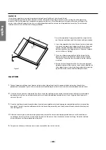
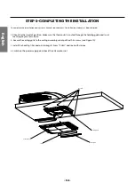
sponge (Num3,5mm)
foam (Num 3, 14mm)
foam (under)
foam
fig 5-2
foam
wind-path
fig 5-3
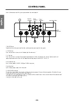
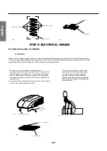
1. As shown in fig.7, the outdoor unit has two sets of
outgoing wires, which are power cord (high current) and the
control signal wires respectively. The former one should be
directly connected to the power supply terminal while the
latter one should be connected to the control signal wire of
the indoor unit.
2. As shown in fig.8, the indoor unit has one set of control signal
wires, with 4 wiring terminals in total.
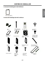
3. As shown in the picture, connect the
wiring terminals of indoor and outdoor
units one by one. Then use a piece of
sponge to wrap the wiring terminals
together, with each terminal separately
encircled by the sponge. Avoid gaps bet-
ween each wire.
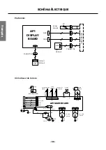
STEP 4-ELECTRICAL WIRING
ROUTING 220-240V AC WIRING
WARNING
Make sure that all power supply to the unit is disconnected before performing any work on the unit to avoid the possibility
of shock or injury and/or damage to the equipment. After the interior ceiling assembly frame is properly secured to the roof
top air conditioner, the following electrical connections must be performed.
outdoor
electrical
wire
indoor electrical wire
display board
fig 8
fig 9
outdoor connect wire
fig 7


