background image

Instruction Book 

9828 0934 73 

45


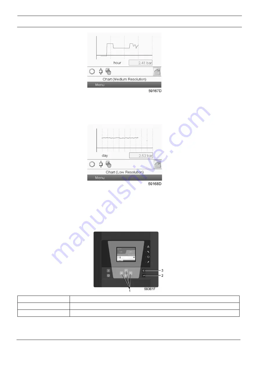
When the Chart (Medium Resolution) is selected, a chart showing the parameter per hour is shown on the 
main screen. Each point is the average of 1 minute. The screen shows 4 hours. 

The  switch  button  (icon)  for  selecting  other  screens  is  changed  into  a  small  Chart  and  is  highlighted 
(active). 

When the Chart (Low Resolution) is selected, a chart showing the parameter per day is shown on the main 
screen. Each point is the average of 1 hour. The screen shows 10 days. 

The switch button (icon) for selecting other screens is changed into a small Chart and is highlighted (active). 

3.5


Calling up menus


Control panel 

(1)


Scroll keys


(2)


Enter key


(3)


Escape key


Summary of Contents for QED 650

Page 1: ...Quincy Refrigerant compressed air dryers QED 650 QED 850 QED 1050 QPVS 650 QPVS 850 QPVS 1050 Air Cooled and Water Cooled Instruction book ...

Page 2: ......

Page 3: ...p Belgium Any unauthorized use or copying of the contents or any part thereof is prohibited This applies in particular to trademarks model denominations part numbers and drawings Use only authorized parts Any damage or malfunction caused by the use of unauthorized parts is not covered by Warranty or Product Liability 02 2021 No 9828 0934 73 Ed 00 ...

Page 4: ...Instruction Book 4 9828 0934 73 ...

Page 5: ...cuit 21 2 3 Refrigeration system 26 2 4 Automatic regulation system 31 2 5 Condensate drain system 35 2 6 Electrical system 37 3 Controller 38 3 1 General 38 3 2 Control panel 39 3 3 Icon used 40 3 4 Main screen 43 3 5 Calling up menus 45 3 6 Inputs menu 47 3 7 Outputs menu 48 3 8 Counters 50 3 9 Event history menu 51 3 10 Modifying settings 52 3 11 Info menu 59 3 12 Week timer menu 60 3 13 Test m...

Page 6: ... Initial start up 101 5 3 Starting 102 5 4 During operation 102 5 5 Stopping 103 6 Maintenance 104 6 1 Preventive maintenance schedule 104 7 Problem solving 106 7 1 Problem solving 106 7 1 1 Faults and remedies general 107 7 1 2 Faults and remedies controller 108 7 1 3 Faults and remedies converter Only for VSD models 108 8 Technical data 111 8 1 Limitations and reference conditions 111 8 2 Air Dr...

Page 7: ...st be adequately purified according to the applicable legislation and standards 5 Before any maintenance repair work adjustment or any other non routine checks Stop the compressor Press the emergency stop button Switch off the voltage Depressurize the compressor Lock Out Tag Out LOTO Open the power isolating switch and lock it with a personal lock Tag the power isolating switch with the name of th...

Page 8: ... explosion 7 Arrange the air intake so that loose clothing worn by people cannot be sucked in 8 Ensure that the discharge pipe from the dryer to the air net is free to expand under heat and that it is not in contact with or close to flammable materials 9 No external force may be exerted on the air outlet valve the connected pipe must be free of strain 10 If remote control is installed the machine ...

Page 9: ...When blowing through a hose or air line ensure that the open end is held securely A free end will whip and may cause injury Make sure that a hose is fully depressurized before disconnecting it 3 Persons switching on remotely controlled machines shall take adequate precautions to ensure that there is no one checking or working on the machine To this end a suitable notice shall be affixed to the rem...

Page 10: ...nce work shall only be undertaken when the machine has cooled down 5 A warning sign bearing a legend such as Work in progress do not start shall be attached to the starting equipment 6 Persons switching on remotely controlled machines shall take adequate precautions to ensure that there is no one checking or working on the machine To this end a suitable notice shall be affixed to the remote starti...

Page 11: ...h the skin rinse the skin with water If liquid refrigerant contacts the skin through clothing never tear off or remove the latter flush abundantly with fresh water over the clothing until all refrigerant is flushed away then seek medical first aid Also consult following safety precautions Safety precautions during installation and Safety precautions during operation These precautions apply to mach...

Page 12: ...tive 2012 19 EU with the crossed out wheelie bin symbol At the end of life time of the electric and electronic equipment EEE it must be taken to separate collection For more information check with your local waste authority customer center or distributor Disposal of other used material Used filters or any other used material e g desiccant lubricants cleaning rags machine parts etc must be disposed...

Page 13: ...egulator 1 keeps the pressure dew point stable at no load by opening or closing the solenoid valve of the hot gas by pass On air cooled dryers the condenser has a cooling fan controlled by a pressure sensor Water cooled dryers have a water regulating valve in the water outlet of the condenser The descriptions mentioned in this book are valid for both air cooled and water cooled dryers General View...

Page 14: ...Instruction Book 14 9828 0934 73 General view of water cooled QED QPVS dryer Reference Description 1 Electronic regulator 2 Grating Position of components Inside view of air cooled QED 650 ES 310 ...

Page 15: ...Instruction Book 9828 0934 73 15 Inside view of air cooled QED 850 ES 410 Inside view of air cooled QPVS 650 ES 310 VSD and QPVS 850 410 VSD ...

Page 16: ...Instruction Book 16 9828 0934 73 Inside view air cooled QED 1050 ES 510 Inside view air cooled QPVS 1050 ES 510 VSD ...

Page 17: ...Instruction Book 9828 0934 73 17 Inside view of water cooled QED 650 ES 310 Inside view of water cooled QPVS 650 ES 310 VSD and QPVS 850 ES 410 VSD ...

Page 18: ...Instruction Book 18 9828 0934 73 Inside view of water cooled QED 850 ES 410 and QED 1050 ES 510 Inside view of water cooled QPVS 1050 ES 510 VSD ...

Page 19: ...dryers air cooled condenser On water cooled dryers water cooled condenser 4 Solenoid valve 5 Cubicle 6 Hot gas by pass valve 7 Refrigerant compressor 8 Liquid separator 9 Electronic water drain 10 Sight glass with moisture indicator 11 Thermostatic expansion valve 12 Refrigerant dryer filter 13 Non return valve 14 Converter Connection Rear view of air cooled dryer ...

Page 20: ... of water cooled dryer Reference Name 1 Compressed air outlet 2 Compressed air inlet 3 Cable gland electrical connection 4 Automatic drain hose 5 Cooling water outlet Only on water cooled dryers 6 Cooling water inlet Only on water cooled dryers ...

Page 21: ...Instruction Book 9828 0934 73 21 2 2 Air circuit Air Flow diagram Air and refrigerant flow diagram for air cooled QED 650 ES 310 QED 850 ES 410 and QED 1050 ES 510 ...

Page 22: ...Instruction Book 22 9828 0934 73 Air and refrigerant flow diagram for air cooled QPVS 650 ES 310 VSD QPVS 850 ES 410 VSD and QPVS 1050 ES 510 VSD ...

Page 23: ...Instruction Book 9828 0934 73 23 Air and refrigerant flow diagram for water cooled QED 650 ES 310 QED 850 ES 410 and QED 1050 ES 510 ...

Page 24: ...Instruction Book 24 9828 0934 73 Air and refrigerant flow diagram for water cooled QPVS 650 ES 310 VSD QPVS 850 ES 410 VSD and QPVS 1050 ES 510 VSD ...

Page 25: ... Enclosure for several components assembled in one unit Second fan blower is installed on QED 1050 ES 510 46 C 115 F Description Compressed air enters heat exchanger 101a and is cooled by the outgoing cold dried air Water in the incoming air starts to condense The air then flows through heat exchanger evaporator 101b where the refrigerant evaporates causing the air to be further cooled to close to...

Page 26: ...Instruction Book 26 9828 0934 73 2 3 Refrigeration system Refrigerant flow diagram Air and refrigerant flow diagram for QED 650 ES 310 QED 850 ES 410 and QED 1050 ES 510 ...

Page 27: ...Instruction Book 9828 0934 73 27 Air and refrigerant flow diagram for air cooled QPVS 650 ES 310 VSD QPVS 850 ES 410 VSD and QPVS 1050 ES 510 VSD ...

Page 28: ...Instruction Book 28 9828 0934 73 Air and refrigerant flow diagram for water cooled QED 650 ES 310 QED 850 ES 410 and QED 1050 ES 510 ...

Page 29: ...Instruction Book 9828 0934 73 29 Air and refrigerant flow diagram for water cooled QPVS 650 ES 310 VSD QPVS 850 ES 410 VSD and QPVS 1050 ES 510 VSD ...

Page 30: ... pressure The heated refrigerant leaves the evaporator and is sucked in by refrigerant compressor 209 via liquid separator 207 The dryers are provided with a sight glass 211 The sight glass allows the refrigerant flow in the line to be checked During normal operation the liquid flow must be clear In general vapor bubbles indicate a shortage of refrigerant Note that fluctuations in the load may cau...

Page 31: ...Instruction Book 9828 0934 73 31 2 4 Automatic regulation system Air and refrigerant flow diagram Air and refrigerant flow diagram for air cooled QED 650 ES 310 QED 850 ES 410 and QED 1050 ES 510 ...

Page 32: ...Instruction Book 32 9828 0934 73 Air and refrigerant flow diagram for air cooled QPVS 650 ES 310 VSD QPVS 850 ES 410 VSD and QPVS 1050 ES 510 VSD ...

Page 33: ...Instruction Book 9828 0934 73 33 Air and refrigerant flow diagram for water cooled QED 650 ES 310 QED 850 ES 410 and QED 1050 ES 510 ...

Page 34: ...d versions the regulator stops and starts the cooling fans For water cooled versions the water regulating valve in the water outlet regulates the cooling water flow When at partial or no load the dew point pressure stays below the set point the regulator opens solenoid valve 210 and hot high pressure gas is fed through hot gas by pass valve 208 to the evaporator circuit to prevent the evaporator t...

Page 35: ...0934 73 35 2 5 Condensate drain system Description Electronic water drain location Electronic water drain functioning Reference Name 1 Inlet 2 Supply line 3 Pilot valve 4 Diaphragm 5 Sensor 6 Collector 7 Valve seat 8 Outlet ...

Page 36: ... water drain starts flashing a warning appears on the display of the regulator and the electronic drain valve will automatically change to the alarm mode opening and closing the valve according to a sequence as shown below This condition continues until the fault is remedied If the fault is not remedied automatically maintenance is required Drain frequency during alarm condition Testing the Electr...

Page 37: ...he compressor motor when the pressure in the refrigerant circuit reaches the upper set point of the switch After tripping The switch must be reset manually by pressing its reset knob and by accessing the protection menu on the electronic regulator and pressing the Enter key The compressor motor has a built in thermic protection If the thermic protection trips the compressor motor will be stopped T...

Page 38: ...n general the regulator has following functions controlling the dryer protecting the dryer automatic restart after voltage failure made inactive Controlling the dryer The regulator keeps the pressure dew point stable at no load by opening or closing the solenoid valve of the hot gas by pass In order to keep the condenser pressure constant For air cooled versions the regulator starts and stops the ...

Page 39: ...voltage A restart delay can also be programmed allowing for example the dryer and the compressors to be restarted one after the other 3 2 Control panel Parts and functions Reference Designation Function 1 Display Shows the dryer operating condition and a number of icons to navigate through the menu 2 Pictograph Automatic operation 3 Pictograph General alarm 4 General alarm LED Flashes if a shut do...

Page 40: ...ands still When the dryer is running the icon is rotating Machine control mode Local start stop Remote start stop Network control Automatic restart after voltage failure Automatic restart after voltage failure is active Week timer Week timer is active Shutdown Warning Service Service required Main screen Change main screen Main chart ...

Page 41: ...34 73 41 Inputs Icons Icon Description Pressure Temperature Digital input Special protection System Icons Icon Description Dryer Fan Frequency converter Drain Filter Motor Failure expansion module Network problem General alarm ...

Page 42: ... Menu icons Icon Description Inputs Outputs Alarms Warnings shutdowns Counters Test Settings Service Event history saved data Access key User password Network Set point Info General settings Navigation arrows Icon Description Up Down ...

Page 43: ... Main screen is shown automatically when the voltage is switched on and one of the keys is pushed It is switched off automatically after a few minutes when no keys are pushed Five different main screens can be chosen 1 Two value lines 2 Four value lines 3 Chart High resolution 4 Chart Medium resolution 5 Chart Low resolution Two and four value views Typical Main screen Two value lines 1 Dryer PDP ...

Page 44: ...orresponds to the selected icon When the menu button is selected this text shows the operational state of the dryer Section D shows the Action buttons These buttons are used to call up or program settings to reset a service message to have access to all data collected by the regulator The function of the buttons depends on the displayed menu The most common functions are Designation Function Menu ...

Page 45: ...for selecting other screens is changed into a small Chart and is highlighted active When the Chart Low Resolution is selected a chart showing the parameter per day is shown on the main screen Each point is the average of 1 hour The screen shows 10 days The switch button icon for selecting other screens is changed into a small Chart and is highlighted active 3 5 Calling up menus Control panel 1 Scr...

Page 46: ... the Scroll keys Press the Enter key to select the menu Following screen appears The screen shows a number of icons Each icon indicates a menu item By default the Inputs icon is selected The status bar shows the name of the menu that corresponds with the selected icon Use the Scroll keys to select an icon Press the Enter key 2 to open the menu or press the Escape key 3 to return to the Main screen...

Page 47: ...n To call up information regarding the actually measured data and the status of some inputs such as the Vessel Pressure Procedure Starting from the main screen see Main screen Move the cursor to the action button Menu and press the Enter key Following screen appears Press the Enter key A screen similar to the one below appears ...

Page 48: ...the first items of a list of all inputs with their corresponding icons and readings Use the scroll button to see the other items in the list If an input is in warning or shutdown the original icon is replaced by the warning or shutdown icon respectively 3 7 Outputs menu Control panel 1 Scroll keys 2 Enter key 3 Escape key Menu icon Outputs ...

Page 49: ...n appears Move the cursor to the Outputs icon using the Scroll keys Press the Enter key A screen similar to the one below appears 1 Outputs 2 Solenoid Valve 1 HGBP1 3 Run Enable Dryer Motor 4 Dryer Fan 1 5 Dryer Fan 2 The screen shows the first items of a list of all outputs with their corresponding icons and readings Use the scroll button to see the other items in the list If an input is in warni...

Page 50: ...e number of dryer starts The number of hours that the regulator has been powered Procedure Starting from the Main screen see Main screen Move the cursor to the action button Menu and press the Enter key Following screen appears Using the Scroll keys move the cursor to the Counters icon see above section Menu icon Press the Enter key Following screen appears ...

Page 51: ...dule hours The screen shows a list of all counters with their actual readings 3 9 Event history menu Control panel 1 Scroll keys 2 Enter key 3 Escape key Menu icon Event History Function To call up the last shut down and last emergency stop data Procedure Starting from the Main screen see Main screen ...

Page 52: ... desired shut down or emergency stop event Press the Enter key to find the date time and other data reflecting the status of the dryer when that shut down or emergency stop occurred 3 10 Modifying settings Control panel 1 Enter key 2 Escape key 3 Scroll keys Menu icon Settings Function To display and modify a number of settings e g Time Date Date format Language units Procedure Starting from the M...

Page 53: ...enu icon Press the Enter key Following screen appears The screen shows a number of icons Icon Function Network settings General settings Regulation settings Automatic restart after voltage failure settings Access key User password Move the cursor to the icon of the function to be modified and press the Enter key ...

Page 54: ...Following screen appears Text on figure 1 Network 2 Ethernet 3 CAN A red selection bar is covering the first item Ethernet Use the key of the Scroll keys to select the setting to be modified and press the Enter key Following screen appears Screen for Ethernet setting Text on figure 1 Ethernet 2 IP Address 3 Subnet mask 4 Gateway IP 5 Modify ...

Page 55: ...ing the Scroll keys move the cursor to the setting to be modified e g Ethernet and press the Enter button 2 A pop up screen appears Use the or key to select the required parameter and press the Enter key to confirm General settings Select the General settings icon as described above and press the Enter button 2 Following screen appears Text on figure 1 General 2 Language in use 3 Time 4 Date 5 Dat...

Page 56: ...s of a list of all settings Use the scroll button to see the other items in the list Press the Enter button 2 a selection bar is covering the first item Dryer operation mode Use the key of the Scroll keys to select the setting to be modified and press the Enter key A pop up screen appears Use the or key to select the required parameter and press the Enter key to confirm It is possible to program t...

Page 57: ... using the scroll key Press the enter button Press the enter button again to modify the security level Press the enter button again a pop up menu appears Use the scroll keys to enter the password of the new security level Press the enter key to confirm the change User password If the password option is activated it is impossible for not authorized persons to modify any setting Using the Scroll key...

Page 58: ...odifying the chart range Select the chart range as described above and proceed as follows Press the enter key the minimum setting becomes highlighted Press the enter key to modify the minimum setting or use the arrow down key to modify the maximum setting Press the enter key to accept the modification Modifying the chart band Select the chart band as described above and proceed as follows Press th...

Page 59: ...on To show the internet address Procedure Starting from the Main screen see Main screen Move the cursor to the action button Menu and press the Enter key Following screen appears Using the Scroll keys move the cursor to the Info icon see above section Menu icon Press the Enter key The internet address appears on the screen ...

Page 60: ...ek schemes can be programmed A week cycle can be programmed a week cycle is a sequence of 10 weeks For each week in the cycle one of the four programmed week schemes can be chosen Procedure Starting from the Main screen see Main screen Move the cursor to the action button Menu and press the Enter key Use the Scroll buttons to select the Timer icon Press the Enter key on the controller Following sc...

Page 61: ... Programming week schemes Select Week action schemes and press Enter A new window opens The first item in the list is highlighted in red Press the Enter key on the controller to modify Week Action Scheme 1 Text on figure 1 Week Action Schemes 2 Week Action Scheme 1 3 Week Action Scheme 2 4 Week Action Scheme 3 5 Week Action Scheme 4 A weekly list is shown Monday is automatically selected and highl...

Page 62: ... the controller to create an action Text on figure 1 Monday 2 Modify A new pop up window opens Select an action from this list by using the Scroll keys on the controller When ready press the Enter key to confirm A new window opens The action is now visible in the first day of the week Text on figure 1 Monday 2 Start 3 Save 4 Modify To adjust the time use the Scroll keys on the controller and press...

Page 63: ... window opens Use the or key of Scroll keys to modify the values of the hours Use the or Scroll keys to modify the minutes Text on figure 1 Monday 2 Time 3 Save 4 Modify Press the Escape key on the controller The action button Modify is selected Use the Scroll keys to select the action Save ...

Page 64: ...ons Press the Enter key to confirm Text on figure 1 Monday 3 Are you sure 4 No 5 Yes 6 Save 7 Modify Press the Escape key to leave this window The action is shown below the day the action is planned Text on figure 1 Week Action Scheme 1 2 Monday Start 3 Tuesday 4 Wednesday 5 Thursday 6 Friday 7 Saturday 8 Sunday Press the Escape key on the controller to leave this screen ...

Page 65: ... one of the four programmed week schemes can be chosen Select Week Cycle from the main Week Timer menu list Text on figure 1 Week Timer 2 Week Action Schemes 3 Week Cycle 4 Status 5 Week Timer Inactive 6 Remaining Running Time A list of 10 weeks is shown Text on figure 1 Week Cycle 2 Week 1 3 Week 2 4 Week 3 5 Week 4 6 Modify ...

Page 66: ... 3 Week Action Scheme 1 4 Week Action Scheme 2 5 Week Action Scheme 3 6 Modify Check the status of the Week Timer Use the Escape key on the controller to go back to the main Week Timer menu Select the status of the Week Timer Text on figure 1 Week Timer 2 Week Action Schemes 3 Week Cycle 4 Status 5 Week Timer Inactive 6 Remaining Running Time A new window opens Select Week 1 to set the Week Timer ...

Page 67: ...e 1 Week Timer 2 Week 3 Week Timer Inactive 4 Week 1 Press the Escape key on the controller to leave this window The status shows that week 1 is active Text on figure 1 Week Timer 2 Week Action Schemes 3 Week Cycle 4 Status 5 Remaining Running Time ...

Page 68: ...Modify Text on figure 1 Week Timer 2 Week Action Schemes 3 Week Cycle 4 Status 5 Remaining Running Time This timer is used when the week timer is set and for certain reasons the dryer must continue working The remaining running time for example 1 hour can be set in this screen This timer is prior to the Week Timer action Text on figure 1 Week Timer 2 Week action schemes 3 Remaining Running Time ...

Page 69: ...n screen see Main screen Move the cursor to the action button Menu and press the enter key 2 following screen appears Using the scroll keys 1 move the cursor to the test icon see above section Menu icon Press the enter key 2 following screen appears A selection bar is covering the item drain test press the enter key A screen is shown to start draining ...

Page 70: ...Service menu Control panel 1 Scroll keys 2 Enter key 3 Escape key Menu icon Service Function To reset the service plans which are carried out To check when the next service plans are to be carried out To find out which service plans were carried out in the past To modify the programmed service intervals Procedure Starting from the Main screen see Main screen Move the cursor to the action button Me...

Page 71: ... of running hours is 4000 hours upper row green and the programmed number of real time hours is 4380 hours which corresponds to six months second row blue This means that the controller will launch a service warning when either 4000 running hours or 4380 real hours are reached whichever comes first Note that the real time hours counter keeps counting also when the controller is not powered The fig...

Page 72: ...ached a message will appear on the screen After carrying out the service actions related to the indicated levels the timers must be reset From the Service menu above select Service plan 3 and press Enter Following screen appears Text on figure 1 Service plan 2 Level 3 Running hours 4 Real time Next Service Text on figure 1 Next service 2 Level 3 Running hours 4 Actual Inthe example above the A Ser...

Page 73: ... time hours use the Scroll keys to select the desired action and press the Enter key 3 15 Converter menu Control panel 1 Scroll keys 2 Enter key 3 Escape key Menu icon Test Function To call up the speed of the refrigerant compressor Procedure Starting from the Main screen see Main screen Move the cursor to the action button Menu and press the enter key 2 Following screen appears Using the scroll k...

Page 74: ...gerant compressor appears 3 16 Protections menu Control panel 1 Scroll keys 2 Enter key 3 Escape key Menu icon Protections Function To call up and to reset the protections Before resetting a warning or shut down message always remedy the problem Frequently resetting these messages without remedying may damage the dryer ...

Page 75: ...appears Using the scroll keys 1 move the cursor to the protections icon see above section Menu icon Press the enter key 2 Following screen appears The screen shows a list of all shut down and shut down warning settings and the actual reading In case of shut down the protection can be reset after remedying 3 17 Extra menu Control panel 1 Scroll keys 2 Enter key 3 Escape key ...

Page 76: ...ure Starting from the Main screen see Main screen Move the cursor to the Menu action button and press the enter key 2 Following screen appears Using the scroll keys 1 move the cursor to the Extra icon see above section Menu icon Press the enter key 2 A screen showing the actual readings for the pressure dewpoint the relative humidity and the LAT setpoint appears ...

Page 77: ...s allows to consult certain data and settings via a PC instead of via the display of the controller Getting started Make sure you are logged in as administrator Use the internal network card from your computer or a USB to LAN adapter see picture below USB to LAN adapter Use a UTP cable CAT 5e to connect to the controller see picture below Configuration of the network card Go to My Network places 1...

Page 78: ...ction 1 which is connected to the controller Click with the right button and select properties 1 Use the checkbox Internet Protocol TCP IP 1 see picture To avoid conflicts de select other properties if they are selected After selecting TCP IP click on the Properties button 2 to change the settings ...

Page 79: ...Instruction Book 9828 0934 73 79 Use the following settings IP Address 192 168 100 200 Subnetmask 255 255 255 0 Click OK and close network connections ...

Page 80: ...internal web server When using Opera or Firefox a redirect page opens Click on the hyperlink to connect to the download server from Microsoft to download the latest version of Internet Explorer and install this software When using Internet Explorer Open Internet Explorer and click on Tools Internet options 2 Click on the Connections tab 1 and then click on the LAN settings button 2 In the Proxy se...

Page 81: ...ose that you already added two IP addresses 192 168 100 1 and 192 168 100 2 Now you add 192 168 100 100 and separate the 3 IP addresses by putting semicolons between them 1 see picture Click OK 2 to close the window Viewing the controller data Open your browser and type the IP address of the controller you want to view in your browser in this example http 192 168 100 100 The interface opens ...

Page 82: ...rom the navigation menu Counters give an overview of all actual counters from controller and dryer Info status the machine status is always shown on the web interface Digital inputs gives an overview of all digital inputs and their status Digital outputs shows a list of all digital outputs and their status Special protections give an overview of all special protections of the compressor Service pl...

Page 83: ...Instruction Book 9828 0934 73 83 4 Installation 4 1 Dimension drawings Dimension drawings Dimension drawing of air cooled QED 650 ES 310 QPVS 650 ES 310 VSD imperial units ...

Page 84: ...Instruction Book 84 9828 0934 73 Dimension drawing of air cooled QED 650 ES 310 QPVS 650 ES 310 VSD metric units ...

Page 85: ...Instruction Book 9828 0934 73 85 Dimension drawing of water cooled QED 650 ES 310 QPVS 650 ES 310 VSD metric units ...

Page 86: ...Instruction Book 86 9828 0934 73 Dimension drawing of water cooled QED 650 ES 310 QPVS 650 ES 310 VSD imperial units ...

Page 87: ...Instruction Book 9828 0934 73 87 Dimension drawing of air cooled QED 850 ES 410 QPVS 850 ES 410 VSD QPVS 1050 ES 510 VSD imperial units ...

Page 88: ...Instruction Book 88 9828 0934 73 Dimension drawing of air cooled QED 850 ES 410 QPVS 850 ES 410 VSD QPVS 1050 ES 510 VSD metric units ...

Page 89: ...Instruction Book 9828 0934 73 89 Dimension drawing of air cooled QED 1050 ES 510 imperial units ...

Page 90: ...Instruction Book 90 9828 0934 73 Dimension drawing of air cooled QED 1050 ES 510 metric units ...

Page 91: ...Instruction Book 9828 0934 73 91 Dimension drawing of water cooled QED 850 ES 410 QPVS 850 ES 410 VSD QPVS 1050 ES 510 VSD QED 1050 ES 510 imperial units ...

Page 92: ...Instruction Book 92 9828 0934 73 Dimension drawing of water cooled QED 850 ES 410 QPVS 850 ES 410 VSD QPVS 1050 ES 510 VSD QED 1050 ES 510 metric units ...

Page 93: ... 2 Electrical connection cable gland M25 3 ISO7 R3 or 3 NPT 4 Cooling air out 5 Cooling air in 6 Net mass approx 7 Compressed air inlet 8 Compressed air outlet 9 Air cooled dryer type 10 Ambient 11 Maximum ambient 12 ISO 7 R 3 4 2x or 3 4 NPT 13 Water cooled dryer type 14 Anchor bolt 15 4x2 holes in anchor plate ...

Page 94: ...Instruction Book 94 9828 0934 73 4 2 Installation proposal Example Installation proposal metric unit ...

Page 95: ...Instruction Book 9828 0934 73 95 Installation proposal for water cooled metric unit Reference Description 1 Ventilation air inlet 2 Ventilation air outlet fan ...

Page 96: ...ver of 0 1 mg m3 0 1 ppm can be installed 2c A high efficiency filter may be installed downstream of the refrigerant dryer This filter traps particles down to 0 01 micron with a max oil carry over of 0 01 mg m3 0 01 ppm 3 Air receiver with condensate drain 4 Pressure gauge 5 Condensate drain 6 Dryer outlet valve 7 By pass system 8 By pass valve 9 Dryer inlet valve 10 Electronic water drain 4 3 Ins...

Page 97: ... dryer free If necessary take action to avoid external influences wind draughts etc through the ventilation gratings of the dryer as they may disturb the cooling air flow For the reference of components see the section Installation proposal For water cooled dryer The inlet grid s 1 and ventilation fan 2 if provided should be installed in such a way that natural circulation of air is guaranteed The...

Page 98: ...struction accessing the unit through the removable panels 4 4 Electrical cable size and fuses Important Local regulations remain applicable if they are stricter than the values proposed For 50 Hz dryers the settings of the main fuses below are according to Directive 73 23 EEC low voltage directive EN60204 83 336 EC electromagnetic compatibility The cable size is valid for cable PVC 70 C 158 F at a...

Page 99: ...6 A QPVS 1050 ES 510 VSD 400 V 3 x 16 A Electrical cable size Dryer Supply voltage Supply cable section recommended QED 650 ES 310 400 V 3 x 4 mm2 4 mm2 QPVS 650 ES 310 VSD 400 V 3 x 4 mm2 4 mm2 QED 850 ES 410 400 V 3 x 4 mm2 4 mm2 QPVS 850 ES 410 VSD 400 V 3 x 4 mm2 4 mm2 QED 1050 ES 510 400 V 3 x 4 mm2 4 mm2 QPVS 1050 ES 510 VSD 400 V 3 x 4 mm2 4 mm2 QED 650 ES 310 460 V 3 X AWG 12 AWG 12 QPVS 6...

Page 100: ...ly for 60 Hz units 2 Warning voltage 3 Cooling water outlet Only for water cooled dryers 4 Cooling water inlet Only for water cooled dryers 5 Maximum air inlet temperature of 70 C 158 F 6 Switch off and depressurise the dryer before starting maintenance or repair 7 Compressed air inlet 8 Dry air outlet 9 Automatic condensate drain ...

Page 101: ...t least 10 minutes before starting the main supply to the dryer must be switched on to initialize the regulator and flow switch 2 Press start button 14 Three phase fix speed units are provided with a phase sequence relay When the dryer compressor motor does not start switch off the voltage and reverse two incoming electric lines Check the rotation direction of the fan motor s The correct rotation ...

Page 102: ...he dryer air inlet valve customer s installation Approx 5 minutes later open the dryer air outlet valve customer s installation Approx 10 minutes later the nominal dew point will be reached 5 4 During operation Description for regulator as shown Regularly check The pressure dew point on the display of the control panel The pressure dew point will deviate from nominal if the air inlet conditions or...

Page 103: ...g Procedure for regulator as shown Procedure Step Action 1 Close dryer inlet and outlet valves customer s installation 2 Press stop button 13 The dryer stops Voltage on LED 8 remains lit Leave the voltage on if the dryer has to remain on stand by ...

Page 104: ... will also cause freezing of the eyes therefore safety glasses must be worn Refrigerant R410a is poisonous Do not inhale refrigerant vapors Check that the working area is adequately ventilated When removing the side panels of the dryer be aware that internal elements such as the pipes can reach a temperature of 120 C 248 F Therefore wait until the dryer has cooled down before removing the side pan...

Page 105: ...ce Plan A Total Responsibility Plan Contact your Customer Center to arrange a tailor made service agreement This will ensure optimum operational efficiency minimize downtime and reduce the total life cycle costs General The following remarks should be kept in mind Keep the dryer clean Brush or blow off the finned surface of the condenser regularly Inspect and clean the electronic water drain once ...

Page 106: ...malfunction caused by the use of unauthorized parts is not covered by Warranty or Product Liability Apply all relevant Safety precautions Before carrying out any maintenance or repairs on the dryer stop the dryer and switch off the voltage Open the isolating switch to prevent an accidental start Isolate the dryer from the air net and depressurize by opening valve 5 on inlet collector 6 ...

Page 107: ...tor Ambient temperature too high Check and correct if necessary draw cooling air via a duct from a cooler place or relocate dryer Condenser externally clogged Clean condenser Compressor stops or does not start Electric power supply to compressor is interrupted Check and correct as necessary Motor overload protection of refrigerant compressor motor has tripped Have motor checked For resetting see t...

Page 108: ... compressor discharge temperature too high Too high load Reduce air flow Shortage of refrigerant Have circuit checked for leaks and recharged 7 1 3 Faults and remedies converter Only for VSD models Fault Description Cause What to do A2B1 Overcurrent Output current has exceeded internal fault limit In addition to an actual overcurrent situation this warning may also be caused by an earth fault or s...

Page 109: ...330 Earth leakage Drive has detected load unbalance typically due to earth fault in motor or motor cable Check motor and motor cable for cabling errors Check motor and motor cable Check for an earth fault in motor or motor cables by measuring the insulation resistances of motor and motor cable see reference value 2340 Short circuit Short circuit in motor cable s or motor Check motor and motor cabl...

Page 110: ...n s Replace fan if faulty Make sure the front cover of the drive is in place and tightened Reboot the control unit 5090 STO hardware failure STO hardware diagnostics has detected hardware failure Replace the drive 5091 Safe torque off Programmable fault 31 22 STO indication run stop Safe torque off function is active i e safety circuit signal s connected to connector STO is broken during start or ...

Page 111: ...ir 100 1 Referred to absolute pressure of 1 bar 14 5 psi and temperature of 20 C 68 F and measured according to ISO 7183 2 At other working conditions see AHB 2933 1870 00 Tab 17 Limitations Limitation Unit Value Maximum compressed air inlet pressure bar e 14 Maximum compressed air inlet pressure psig 203 05 Minimum maximum ambient air temperature C 0 46 Minimum maximum ambient air temperature F 3...

Page 112: ...S 310 QED850 ES 410 QED1050 ES 510 Pressure dewpoint air outlet Ambient air temperature 25 C Compressed air inlet temperature 35 C C 3 3 3 Ambient air temperature 77 F Compressed air inlet temperature 95 F F 37 4 37 4 37 4 Ambient air temperature 30 C Compressed air inlet temperature 40 C C 3 4 4 Ambient air temperature 86 F Compressed air inlet temperature 104 F F 37 4 39 2 39 2 Ambient air tempe...

Page 113: ...al power input of fan s hp 0 5 0 8 1 1 Cooling air flow approx l s 1500 2200 3200 Cooling air flow approx cfm 3178 4662 6780 Heat dissipated by cooling medium flow approx Ambient air temperature 25 C Compressed air inlet temperature 35 C kW 9 12 15 Ambient air temperature 77 F Compressed air inlet temperature 95 F hp 12 2 16 3 20 4 Ambient air temperature 30 C Compressed air inlet temperature 40 C...

Page 114: ...emperature 104 F Compressed air inlet temperature 122 F F 55 4 51 8 42 8 Ambient air temperature 46 C Compressed air inlet temperature 56 C C 19 22 13 Ambient air temperature 115 F Compressed air inlet temperature 133 F F 66 2 71 6 55 4 Total electrical power input Ambient air temperature 38 C Compressed air inlet temperature 38 C kW 4 6 6 1 9 1 Ambient air temperature 100 F Compressed air inlet t...

Page 115: ...Ambient air temperature 77 F Compressed air inlet temperature 95 F hp 13 4 18 8 22 8 Ambient air temperature 30 C Compressed air inlet temperature 40 C kW 12 16 19 Ambient air temperature 86 F Compressed air inlet temperature 104 F hp 16 1 21 5 25 5 Ambient air temperature 35 C Compressed air inlet temperature 45 C kW 14 18 23 Ambient air temperature 95 F Compressed air inlet temperature 113 F hp ...

Page 116: ...ng water inlet of 40 C 104 F Unit At ambient temperature of C 25 30 35 40 At ambient temperature of F 77 86 95 104 Volume flow at dryer inlet under nominal conditions l s 310 310 310 310 Volume flow at dryer inlet under nominal conditions cfm 656 85 656 85 656 85 656 85 Pressure dew point C 3 7 12 18 Pressure dew point F 37 4 44 6 53 6 64 4 Total power consumption kW 2 2 2 3 2 3 2 3 Total power co...

Page 117: ...ling water inlet of 40 C 104 F Unit At ambient temperature of C 25 30 35 40 At ambient temperature of F 77 86 95 104 Volume flow at dryer inlet under nominal conditions l s 410 410 410 410 Volume flow at dryer inlet under nominal conditions cfm 868 74 868 74 868 74 868 74 Pressure dew point C 3 8 13 19 Pressure dew point F 37 4 46 4 55 4 66 2 Total power consumption kW 2 6 2 7 2 7 2 7 Total power ...

Page 118: ...essure dew point C 3 3 5 11 19 Total power consumption hp 4 2 4 2 4 2 4 2 4 3 Total power consumption kW 3 1 3 1 3 1 3 1 3 2 Cooling water flow approx cfm 0 4 0 6 0 6 0 6 0 6 Cooling water flow approx l s 0 2 0 3 0 3 0 3 0 3 Heat dissipated by cooling water flow approx Btu hr 37600 37600 41000 47800 51200 Heat dissipated by cooling water flow approx kW 11 11 12 14 15 Cooling water flow at 25 C 77 ...

Page 119: ...0 41000 44400 51200 Heat dissipated by cooling water flow kW 11 11 12 13 15 QED 1050 ES 510 water cooled 50 Hz version Performance data with cooling water inlet of 25 C 77 F Unit At ambient temperature of C 25 30 35 40 At ambient temperature of F 77 86 95 104 Volume flow at dryer inlet under nominal conditions l s 510 510 510 510 Volume flow at dryer inlet under nominal conditions cfm 1080 63 1080...

Page 120: ... flow approx l s 1 2 1 3 1 4 1 5 Cooling water flow approx cfm 2 54 2 75 2 97 3 18 Heat dissipated by cooling water flow approx kW 13 16 17 19 Heat dissipated by cooling water flow Btu hr 44369 54608 58021 64847 Cooling water flow at 40 C 104 F water inlet approx and a temperature difference of 3 C 5 4 F QED 1050 ES 510 water cooled 60 Hz version Performance data with cooling water inlet of 25 C 7...

Page 121: ...emperature of F 77 86 95 104 Volume flow at dryer inlet under nominal conditions l s 510 510 510 510 Volume flow at dryer inlet under nominal conditions cfm 1080 63 1080 63 1080 63 1080 63 Pressure dew point C 3 4 10 17 Pressure dew point F 37 4 39 2 50 62 6 Total power consumption kW 4 2 4 3 4 3 4 4 Total power consumption hp 5 63 5 77 5 77 5 9 Cooling water flow approx l s 1 2 1 3 1 4 1 5 Coolin...

Page 122: ...ling water flow approx kW 15 14 16 20 22 Cooling water flow at 25 C 77 F water inlet approx and a temperature difference of 10 C 18 F Performance data with cooling water inlet of 40 C 104 F Unit At ambient temperature of F 100 77 86 95 104 At ambient temperature of C 38 25 30 35 40 Volume flow at dryer inlet under nominal conditions cfm 1080 1080 1080 1080 1080 Volume flow at dryer inlet under nom...

Page 123: ...perature 104 F Compressed air inlet temperature 122 F F 77 0 77 0 77 0 Lowest dewpoint mode Ambient air temperature 25 C Compressed air inlet temperature 35 C C 3 3 3 Ambient air temperature 77 F Compressed air inlet temperature 95 F F 37 4 37 4 37 4 Ambient air temperature 40 C Compressed air inlet temperature 50 C C 17 17 20 Ambient air temperature 104 F Compressed air inlet temperature 122 F F ...

Page 124: ...let temperature 35 C kW 8 0 9 8 12 2 Ambient air temperature 77 F Compressed air inlet temperature 95 F Btu hr 27297 33439 41628 Ambient air temperature 40 C Compressed air inlet temperature 50 C kW 14 2 18 5 22 4 Ambient air temperature 104 F Compressed air inlet temperature 122 F Btu hr 48452 63125 76432 Maximum saving mode Ambient air temperature 25 C Compressed air inlet temperature 35 C kW 7 ...

Page 125: ...perature 35 C C 3 3 3 Ambient air temperature 77 F Compressed air inlet temperature 95 F F 37 4 37 4 37 4 Ambient air temperature 38 C Compressed air inlet temperature 38 C C 4 4 4 Ambient air temperature 100 F Compressed air inlet temperature 100 F F 39 2 39 2 39 2 Ambient air temperature 40 C Compressed air inlet temperature 50 C C 17 17 20 Ambient air temperature 104 F Compressed air inlet temp...

Page 126: ...rature 25 C Compressed air inlet temperature 35 C kW 8 0 9 8 12 2 Ambient air temperature 77 F Compressed air inlet temperature 95 F Btu hr 27297 33439 41628 Ambient air temperature 40 C Compressed air inlet temperature 50 C kW 14 2 18 5 22 4 Ambient air temperature 104 F Compressed air inlet temperature 122 F Btu hr 48452 63125 76432 Maximum saving mode Ambient air temperature 25 C Compressed air...

Page 127: ... air inlet temperature 122 F Cooling water inlet temperature 104 F F 68 68 68 Maximum saving mode Ambient air temperature 25 C Compressed air inlet temperature 35 C Cooling water inlet temperature 25 C C 10 10 10 Ambient air temperature 77 F Compressed air inlet temperature 95 F Cooling water inlet temperature 77 F F 50 50 50 Ambient air temperature 40 C Compressed air inlet temperature 50 C Cooli...

Page 128: ...nlet temperature 77 F hp 1 82 2 68 3 31 Ambient air temperature 40 C Compressed air inlet temperature 50 C Cooling water inlet temperature 40 C kW 2 47 3 19 3 5 Ambient air temperature 104 F Compressed air inlet temperature 122 F Cooling water inlet temperature 104 F hp 3 31 4 28 4 69 Maximum saving mode Ambient air temperature 25 C Compressed air inlet temperature 35 C Cooling water inlet tempera...

Page 129: ...mbient air temperature 77 F Compressed air inlet temperature 95 F Cooling water inlet temperature 77 F cfm 0 42 0 64 0 85 Ambient air temperature 40 C Compressed air inlet temperature 50 C Cooling water inlet temperature 40 C l s 1 5 1 3 1 5 Ambient air temperature 104 F Compressed air inlet temperature 122 F Cooling water inlet temperature 104 F cfm 3 18 2 75 3 18 Maximum saving mode Ambient air ...

Page 130: ...temperature 35 C Cooling water inlet temperature 25 C kW 7 5 9 6 11 9 Ambient air temperature 77 F Compressed air inlet temperature 95 F Cooling water inlet temperature 77 F Btu hr 25591 32757 40605 Ambient air temperature 40 C Compressed air inlet temperature 50 C Cooling water inlet temperature 40 C kW 13 1 17 3 19 9 Ambient air temperature 104 F Compressed air inlet temperature 122 F Cooling wa...

Page 131: ...ure 122 F Cooling water inlet temperature 104 F Btu hr 48794 63125 71314 Refrigerant gas and global warming potential The refrigerant gas for the dryer is R410A and the global warming potential is 2088 Amount of refrigerant gas and kilograms of CO2 equivalent for air cooled dryers Dryer Amount kg Amount lbs CO2 equivalent QED650 ES 310 2 0 4 41 4176 QPVS650 ES 310 VSD 1 85 4 08 3863 QED850 ES 410 ...

Page 132: ...air cooled 218 481 QED650 QPVS650 ES 310 ES 310 VSD water cooled 200 441 QED850 QPVS850 ES 410 ES 410 VSD air cooled 240 529 QED850 QPVS850 ES 410 ES 410 VSD water cooled 245 540 QED1050 QPVS1050 ES 510 ES 510 VSD air cooled 265 584 QED1050 QPVS1050 ES 510 ES 510 VSD water cooled 265 584 ...

Page 133: ...ubject to 2014 68 EU Pressure Equipment Directive Components subject to 2014 68 EU Pressure Equipment Directive greater than or equal to category II Description PED Class Compressor II Heat exchanger II High pressure switch IV Overall rating The dryers conform to PED category II ...

Page 134: ...02 2021 No 9828 0934 73 Ed 00 ...

Reviews: