background image

ENGLISH 

.  

Cod. 9828093052  04 - Edition 02/2018 - 17


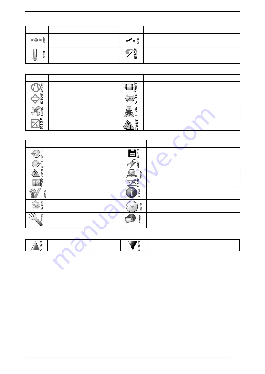
Input icons 

Icon 

Description 

Icon 

Description 


 Pressure 


 Digital input  


 Temperature 


 Special protection 


System icons 


Menu icons 

Icon 

Description 

Icon 

Description 


 Inputs 


 Event history (saved data) 


 Outputs 


 Access key / User password 


 Protections (Warnings, shutdowns) 


 Network 


 Counters 


 Setpoint 


 Test 


 Information 


 Regulation (Settings) 


 Week Timer 


 Service 


 General 


Navigation arrows 


Main screen 

Function 

The Main screen is the screen that is shown automatically when the voltage is switched on and one of the keys is pushed. It is switched off 

automatically after a few minutes when no keys are pushed. 

Typically, 5 different main screen views can be chosen: 


Two value lines 


Four value lines 


Chart (High resolution) 


Chart (Medium resolution) 


Chart (Low resolution) 


Two and four value lines screens 

This type of Main screen shows the value of 2 or 4 parameters (see section Inputs menu). 

Icon 

Description 

Icon 

Description 


 Compressor element (LP, HP, ...) 


 Motor 


 Dryer 


 Failure expansion module 


 Fan 


 Network problem 


 Frequency converter 


 General alarm 


Up 


Down 

Summary of Contents for HP 15

Page 1: ...RAL ORDINARY MAINTENANCE REQUIRES TRAINED PERSONNEL 3 0 OPERATION 22 0 CHANGING THE OIL 4 0 GENERAL SAFETY STANDARDS 23 0 CHANGING THE OIL SEPARATING FILTER 5 0 DESCRIPTION OF DANGER SIGNALS 24 0 OLEO...

Page 2: ...ESEEN FROM THE EUROPEAN STANDARD 2006 42 CE THE LUBRICATING LIQUIDS AND OTHER EVENTUAL FLUIDS MUST NOT BE DISCHARGED IN THE ENVIRONMENT THESE POLLUTING AND HAZARDOUS PRODUCTS MUST COMPULSORY BE DISPOS...

Page 3: ...nt to two separate coolers where they are cooled using a flow of air taken from the environment by a special fan inside the machine The cooled oil returns to the circuit while the compressed air passe...

Page 4: ...1 FLUID EJECTION 6 HOT PARTS 2 DANGEROUS ELECTRIC VOLTAGE 7 MOVING PARTS 3 AIR NOT FIT FOR BREATHING 8 MOVING PARTS 4 NOISE 9 MACHINE WITH AUTOMATIC START 5 HIGH PRESSURE 10 PURGE EVERY DAY 5 1 DESCRI...

Page 5: ...ENGLISH Cod 9828093052 04 Edition 02 2018 5 6 0 DANGERS ZONES 6 1 DANGERS ZONES FOR COMPRESSOR UNIT Risks present on the whole machine 1 2 3 7 8 5 2 2 8 2 2 1 3 8 2 5 3 FIG 3...

Page 6: ...MPRESSOR 1 Safety screws 4 Emergency stop button with mechanical seal and rotation release 2 Side panels and door to the electric panel opened with a special key 5 Oil filling cap with safety breather...

Page 7: ...tomatic 6 Safety valve POSITION OF PLATES 8 1 POSITION OF THE DANGER PLATES FOR COMPRESSOR UNIT The plates fitted on the compressor unit are part of the machine they have been applied for safety purpo...

Page 8: ...ey have been applied for safety purposes and must not be removed or spoiled for any reason 1 Dangers plate Cod 1079990148 8 3 POSITION OF THE DATA PLATE FOR COMPRESSOR UNIT ELECTRICAL AND UL LABELS 1...

Page 9: ...ning must be low to allow the intake of external air for ventilation If the environment is dusty it is advisable to fit a filtering panel on this opening 9 3 EXAMPLES OF VENTILATION OF THE COMPRESSOR...

Page 10: ...iagram Connect the cables to the charging clamps on the electric panel and make sure they are properly tightened After the first 50 working hours check that the screws on the electric terminals are ti...

Page 11: ...ted Drainage must comply with the local regulations in force ALL DAMAGE DUE TO THE FAILURE TO COMPLY WITH THESE INDICATIONS CANNOT BE ATTRIBUTED TO THE MANUFACTURER AND MAY CAUSE INVALIDITY OF THE GUA...

Page 12: ...6 Weight lb with air receiver 120 Gal with dryer 1760 1777 1892 1927 Weight lb without dryer 1052 1069 1135 1171 Weight lb with air receiver 120 Gal without dryer 1553 1570 1636 1672 HP 15 kW 11 HP 20...

Page 13: ...sure gauge tank 14 Control card 15 Safety valve 16 Water separator drain 17 Electric motor 18 Screw compressor 19 Suction unit 20 Condensate manual drainage IT IS FORBIDDEN TO TAMPER WITH THE SETTING...

Page 14: ...ected by temperature sensor compressor element outlet temperature bigger than the programmed shut down level detected by temperature switches overload of the drive motor overload of the fan motor freq...

Page 15: ...ymbol 9 LED Service It s lit when service is needed 10 Start button This button starts the compressor Automatic operation LED 3 lights up The Elektronikon is operative 11 Stop button This button is us...

Page 16: ...pped Running unloaded Running loaded Machine control mode Or Local start stop Remote start stop Network control Automatic restart after voltage failure Automatic restart after voltage failure is activ...

Page 17: ...The Main screen is the screen that is shown automatically when the voltage is switched on and one of the keys is pushed It is switched off automatically after a few minutes when no keys are pushed Typ...

Page 18: ...This bar shows the text that corresponds to the selected icon Section D shows the Action buttons These buttons are used To call up or program settings To reset a motor overload service message or emer...

Page 19: ...w triangle 1 pops up in the lower side of the display as in the picture below in the left side To check which is the warning highlight the yellow triangle using the Scroll keys Press the Enter key and...

Page 20: ...tections and the one who is causing the shutdown will be highlighted as in picture below Take care that the shut down Overload motor appears in case of main motor overload or incorrect phase sequence...

Page 21: ...urrent limit is exceeded 14 4 Ground Fault X X Discharge from output phases to ground 16 4096 Short circuit X X Short circuit in the motor or on the motor terminals 17 16 Ctrl word TO X X No communica...

Page 22: ...ion X X Internal fault Contact compressor service 80 Drive initialized X All parameter settings are initialized to default settings 87 Auto DC Braking X The drive is auto DC braking Inputs menu Functi...

Page 23: ...ber of motor starts the number of hours that the regulator has been powered and the number of load cycles Procedure starting from the Main screen see Main screen move the cursor to the action button M...

Page 24: ...e press the enter button on the controller to confirm your selection The new setting is now visible on the main screen See section Used icons for the meaning of the icons Service menu Function to rese...

Page 25: ...the indicated levels the timers must be reset From the Service menu above select Service plan 3 and press Enter Following screen appears In the example above the A Service level is programmed at 4000...

Page 26: ...s required in the same way as described above Event history menu Function to call up the last shut down and last emergency stop data Procedure starting from the Main screen see Main screen move the cu...

Page 27: ...con General menu Function this menu covers a list of general settings Language Time Date Date Format Units Procedure starting from the submenu screen see Modifying general settings using the Scroll ke...

Page 28: ...down level changes to 96 C 204 F The recommended difference between the warning level and shut down level is 10 C 18 F Delay at shut down signal Is the time for which the signal must exist before the...

Page 29: ...ng electrical cables at first 500 hrs Clean the air suction filter Clean the condenser battery on the dryer if fitted Clean the dirt collection filter Check automatic condensation emptying dryer Clean...

Page 30: ...ate flow out When the first traces of oil appear turn off the tap CONDENSATE MUST BE DISPOSED OF IN CONFORMITY WITH THE LOCAL REGULATIONS IN FORCE Check the oil level on the indicator Ref 5 Fig 18 If...

Page 31: ...ed reassemble the filtering panel Ref 1 Fig 19 15 6 CLEANING THE SUCTION FILTER OR CHANGING THE FILTER Switch off the machine with pushbutton Ref 1 Fig 18 in this way the machine stops after idle time...

Page 32: ...ation is correctly emptied from the drainage pipe Ref 3 Close the panel Ref 2 and Ref 10 Fig 20 15 8 CLEAN THE DIRT COLLECTION FILTER FOR COMPRESSOR AND DRYER IF AVAILABLE Proceed as follows Close the...

Page 33: ...e drainage pipe Check manual condensation emptying from the tank to ensure that condensation is correctly emptied from the valve Ref 2 Fig 20A PURGE EVERY DAY AFTER USE CLEAN THE DIRT COLLECTOR FILTER...

Page 34: ...THE COMPRESSED AIR DISTRIBUTION NETWORK The condenser must be cleaned every month Proceed as follows Switch off the machine with pushbutton Ref 1 Fig 21 in this way the machine stops after idle time r...

Page 35: ...time running Turn off the disconnect switch Ref 5 Fig 22 Close the panel Ref 2 and Ref 7 Fig 22 During periods of inactivity the unit must be protected against atmospheric agents dust and humidity wh...

Page 36: ...P 15 kW 11 HP 20 kW 15 HP 25 kW 18 5 HP 30 kW 22 1 Suction air filter 2013400003 2 Oil filter 1625430291 3 Oil separator cartridge 2204149800 4 Filtering panel only VSD 1089955668 5 Air filter 2202260...

Page 37: ...ion device has tripped 2C Temperature switch on element outlet has tripped Verify phases sequence to check possible motor failure environment temperature too high improve ventilation in the compressor...

Page 38: ...d is very hot 55 C 131 F Make reference to 2B Make reference to 2C 3A The cooling circuit is not working with the right gas charge Check if there are leaks of refrigerating gas Charge it again 4 Motor...

Page 39: ...the oil level is not as intended top up with the same oil as the original type If more than 3 months have passed between the inspection in the factory and the date of installation lubricate the screw...

Page 40: ...ot spin in the right direction reverse two mains cables When it rotates in the correct direction the oil level Rif 5 Fig 25 Should drop after 4 or 5 seconds of operation It is very important to rememb...

Page 41: ...ing panel VSD Clean the air suction filter Clean the air filters Every 4000 hours Maintenance kit of the automatic condensate drain dryer Clean the finned surface of the air oil cooler Change the filt...

Page 42: ...chine will switch off PROCEED AS DESCRIBED AT POINT CHAPTER 15 4 THE OLD OIL MUST BE DISPOSED OF IN COMPLIANCE WITH THE REGULATIONS IN FORCE NOTE ON LUBRICANTS When delivered the machine is filled wit...

Page 43: ...306 Capillary tube 105 Safety valve 308 Electronic drain 106 Oil separator 311 Hot gas bypass valve 107 Minimum pressure valve 312 Fan switch 108 After cooler Oil cooler TISHH1 Temperature sensor Tem...

Page 44: ...ERATION COMPRESSOR Evaporat Temperat C F Evaporating Pressure bar psi Evaporating Pressure bar psi Evaporating Pressure bar psi RATED VALUES Temperat 20 C 68 F 1 2 33 8 35 6 R134a 2 1 2 3 30 4 33 3 R4...

Reviews: