16
QUIETCOOLSYSTEMS.COM
14
-2 W
ir
e
Power Source
Black Wires
Together
Red Switch Leg
Two Speed Wiring
Tie White Common WiresTogether
Taped Whit
e Low Speed
Whole House Fans
Tie All Ground & Bare Copper Wires Together
14-2 Wire
8 HOUR
4 HOUR
2 HOUR
1 HOUR
HOLD
Black High Speed
High
OFF
Low
CONSTANT POWER REQUIRED
6.
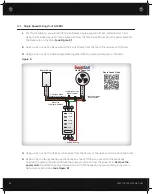
Attach the red leg wire from the timer to the top gold screw on the left of the switch. Finish up the installation of the timer and switch and switch cover plate.
NOTE:
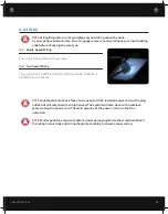
If wiring the ES-3100, ES-4700, ES-5400, ES-6000, or ES-7000 please skip to step
12. If wiring the ES-2250, follow steps 7 through 11
Figure C
Page 1: ...MS COM SEE HEAR FEEL THE QUIETCOOL DIFFERENCE ADVANCED WHOLE HOUSE FANS OWNER S GUIDE ENERGY SAVER CLASSIC LINE DO NOT THROW AWAY SERIAL NUMBER FOR FAN IS LOCATED ON BACK COVER OF OWNER S GUIDE RETAIN...
Page 2: ...be situated away from heat sources 7 Damage Requiring Service Only qualified service personnel should service the QuietCool system The user should not attempt to service the product CONTENTS 1 QUICKS...
Page 3: ...he product Product warranty does NOT cover defective motors resulting from wiring errors 4 DO NOT use any QuietCool ducted whole house fan in a home with all closed windows 5 TEST your QuietCool unit...
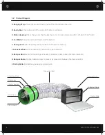
Page 4: ...ee blade fan system E Hand guard Added for safety to keep hands out of the motor housing F Acoustical Duct R 4 2 acoustically lined duct for quiet operation G Damper Box Mounts to the ceiling and hous...
Page 5: ...oo many windows will lessen the cooling breeze you feel The breeze will flow through your home and make its way to each QuietCool you have in operation As it gets later in the evening and even cooler...
Page 6: ...around 75dB that s equivalent to a loud vacuum cleaner running The QuietCool system uses a cutting edge patented design to get our sound levels down to a respectable level Our fans suspend in the atti...
Page 7: ...But don t worry the system will still operate if there is not enough venting Insufficient venting is a very simple problem to fix Roofing contractors can add extra venting to most homes simply and eas...
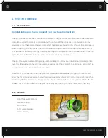
Page 8: ...plate fits between the framing The template size varies depending on which model of QuietCool fan you are installing QuietCool Fan Model Template Size Vertical Adapter Model Sold Separately ES 1500 14...
Page 9: ...out hole TIP If your attic access is far from your fan location you can remove the duct from the motor housing and pass the motor housing duct and damper box through the ceiling cut out hole and reatt...
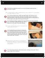
Page 10: ...inside the attic Do not attempt to install the damper box with the flanges on the outer side of the drywall in the home 9 Using the included drywall screws fasten the damper box to the drywall and the...
Page 11: ...installation of this unit NOTE Additional insulation can be added to the top of the damper box to provide additional sound dampening AVOID BACK DRAFTS Care should be taken to avoid back drafting comb...
Page 12: ...the vertical adapter Place the vertical adapter with the T side up onto the damper box with the side that has only two flanges flush on the damper box 2 If you have studs spaced at 16 on center you wi...
Page 13: ...For wiring of the ES 2250 ES 3100 ES 4700 ES 5400 ES 6000 or ES 7000 with two speeds NOTE QuietCool whole house fans can be used with the included power cord with a plug outlet but will only operate...
Page 14: ...fan by opening up the handy box Take off the wire nuts within the handy box Unscrew the green ground wire Detach the green ground wire from the power cord Remove the power cord Re attach the ground s...
Page 15: ...the top gold screw on the right of the switch Then attach the black wire to the bottom gold screw see Figure C 3 With a piece of bare copper wire attach it to the green ground screw on the switch 4 Us...
Page 16: ...her Red Switch Leg Two Speed Wiring Tie White Common Wires Together Taped White Low Speed Whole House Fans Tie All Ground Bare Copper Wires Together 14 2 Wire 8 HOUR 4 HOUR 2 HOUR 1 HOUR HOLD Black Hi...
Page 17: ...ed the 2 wire Romex from your power source into the handy box 10 Tie the three remaining black wires together Tie the three remaining white common wires together Tie the three bare copper wires and th...
Page 18: ...ire Romex from your timer into the handy box Feed the 2 wire Romex from your power source into the handy box 15 Tie the three remaining black wires together Tie the three remaining white common wires...
Page 19: ...f service calls to diagnose the cause of problems or the labor charge to un install any components 3 Product failure or damage due to faulty installtion abuse misuse unauthorized alteration to factory...