background image

15

ENGLISH

Rev.3.0

XENON SA

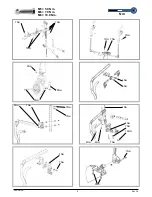
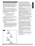
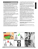
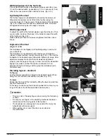
3. The attachment points to the chair are the inner front 

side frame just above the castor, and the rear side frame. 

The straps are fitted around the side frames at the 

intersection of the horizontal and vertical frame tubes. 

(See Figs G - H)

 4. The tie down symbol (Fig F) on the wheelchair frame 

indicates the position of the wheelchair restraint straps. 

The straps are then tensioned after the front straps have 

been fitted to secure the wheelchair.

USER WEIGHT LESS THAN 22 kg (48 lb 8.0 oz)

When the user being transported is a child, less than 

22Kg mass and the vehicle involved has less than eight 

(8) seated passengers it is recommended that they be 

transferred to an UNCE Regulation 44 compliant child 

restraint system (CRS).

This type of restraint system provides a more effective 

occupant restraint system than the conventional 3 point 

occupant restraint system and some CRS systems also 

include additional postural supports to assist in 

maintaining the position of the child when seated.

Parents or care providers may consider the option, in 

some circumstances, for their child is to remain in their 

wheelchair whilst in transport due to the level of posture 

control and comfort provided by the set up in the 

wheelchair.

We would recommend in such circumstances that a risk 

assessment be carried out by your healthcare 

professional and relevant competent persons.

Transportability – positioning of wheelchair tie down 

restraints on wheelchair


The wheelchair secured with front wheelchair tie down 

restraints. (Fig. G).

Position of the rear wheelchair tie down restraint, (Fig H).

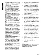
12. The safety of the user during transportation depends 

upon the diligence of the person securing the tie-down 

restraints and they should have received appropriate 

instructions and/or training in their use.

13. Wherever possible remove and stow safely away 

from the wheelchair all auxiliary equipment, for example:

Crutches, Loose cushions and Tray Tables.

14. Articulating/elevating leg rest should not be used in 

the elevated position when the wheelchair and user are 

being transported and the wheelchair is restrained using 

Wheelchair Transport and Occupant Restraints.

15. Reclining backrests should be returned to an upright 

position. 

16. The manual brakes must be firmly applied.

17. Restraints should be mounted to the vehicle “B” pillar 

and should not be held away from the body by wheelchair 

components such as armrest or wheels.

Occupant Restraints Instruction:

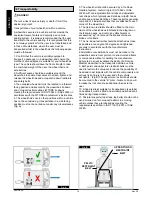
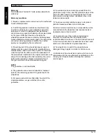
1. The pelvic restraint belt must be worn low across the 

front of the pelvis so that the angle of the pelvic belt is 

within the preferred zone of 30 to 75 degrees to the 

horizontal.

A steeper (greater) angle within the preferred zone is 

desirable i.e. closer to, but never exceeding 75degrees. 

(Fig C).

2. The upper torso restraint belt must fit over the shoulder 

and across the chest as illustrated Fig d and e

Restraint belts must be adjusted as tightly as possible 

consistent with user comfort.

Restraint belt webbing must not be twisted when in use.

The upper torso restraint belt must fit over the shoulder 

and across the shoulder as illustrated in Fig D and E.

Transportability Cont..

Fig.D

Fig.E

Fig.C

PREFERED 

ZONE

Fig.F

Fig. G

Fig. H

Summary of Contents for Xenon SA

Page 1: ...Directions for use Notice d utilisation Gebruikershandleiding Xenon SA Wheelchair Fauteuil roulant Rolstoel 000690675 17...

Page 2: ...ives de la Communaut europ enne Les options ou accessoires illustr s sont disponibles moyennant un co t suppl mentaire FR Wheelchair Components We at SUNRISE MEDICAL have been awarded the ISO 9001 cer...

Page 3: ...es de pouss e 2 Toile de dossier 3 Prot ge v tement 4 Toile d assise 5 Repose pieds 6 Roues avant 7 Palette 8 Fourche 9 Axe d verrouillage rapide 10 Freins 11 Main courante 12 Roue arri re Rolstoelon...

Page 4: ...0 XENON SA 310 270 880 1150 990 760 480 1120 810 MAX mm MIN mm 570 430 500 340 567 540 10 0 10 0 15 0 108 75 110 100 500 220 475 250 460 320 6 0 MAX kg MIN kg 125 9 8 10 0 MAX MIN MAX MIN 130 20 2 1 K...

Page 5: ...440 370 460 460 370 470 470 370 480 480 370 174 x 45 470 470 370 480 480 370 500 500 370 510 510 380 520 520 390 102 mm 4 98 x 32 430 430 370 440 440 370 450 450 370 111 x 32 440 440 370 450 450 370 4...

Page 6: ...450 370 480 470 370 490 480 370 138 x 45 470 460 370 480 470 370 500 480 370 510 490 370 174 x 45 490 480 370 500 490 370 520 500 380 530 520 400 540 530 410 152 mm 6 111 x 45 440 440 370 450 450 370...

Page 7: ...530 530 410 540 540 420 560 560 440 570 570 450 76 mm 3 FROGLEG 450 450 370 470 470 370 480 480 370 102 mm 4 FROGLEG 460 460 370 480 480 370 490 490 370 127 mm 5 FROGLEG 480 480 370 490 490 370 500 50...

Page 8: ...8 Rev 3 0 XENON SA M5 5 0 Nm M6 7 0 Nm M8 10 0 Nm Nm 7Nm 7Nm 7Nm 7Nm 7Nm 2Nm 2Nm 5Nm 25Nm 6Nm 6Nm 7Nm 7Nm 7Nm 5Nm 7Nm 7Nm 7Nm 7Nm 4Nm 4Nm 10Nm 7Nm 5Nm 7Nm 7Nm...

Page 9: ...ou have any questions contact Sunrise Medical either in writing or by telephone Sunrise Medical Thorns Road Brierley Hill West Midlands DY5 2LD England Phone 0845 605 66 88 Fax 0845 605 66 89 www Sunr...

Page 10: ...However all instructions are completely relevant regardless of possible detail differences The manufacturer reserves the right to alter without notice any weights measurements or other technical data...

Page 11: ...tection in hazardous situations To avoid falls and dangerous situations you should first practice using your new wheelchair on level ground with good visibility This wheelchair should be used exclusiv...

Page 12: ...ot fit any unauthorized electronic equipment powered or mechanically operated mobility drives hand bike or any other device that changes the intended use or the structure of the wheelchair Any combina...

Page 13: ...e reflectors on the side and back of the wheelchair are clearly visible We would also recommend that you fit an active light Always be careful with your fingers when working or adjusting the wheelchai...

Page 14: ...tem conforming to ISO 10542 or SAE J2249 with non adjustable front straps and adjustable rear straps which typically use Karabiner clips S hooks and tongue and buckle fittings These restraints general...

Page 15: ...h front wheelchair tie down restraints Fig G Position of the rear wheelchair tie down restraint Fig H 12 The safety of the user during transportation depends upon the diligence of the person securing...

Page 16: ...not transferable 4 The guarantee also covers all repaired or replaced parts for the remaining period of the guarantee for the wheelchair 5 For spare parts which are fitted after the start of the origi...

Page 17: ...wheelchair to the side as this means that the weight is taken off one of the rear wheels Be careful not to get your fingers caught in the cross tube assembly Fit the seat cushion Fig 4 4 Getting into...

Page 18: ...step on the tube to push a wheel chair for example over a kerb or step Fig 6 1 Wheel locks CAUTION Braking power can be affected by incorrect fitting and adjustment of the wheel locks as well as tyre...

Page 19: ...pact wheel locks are underneath the seat sling and are operated by pulling the wheel locks towards the rear in the direction of the tyre For the wheel locks to operate correctly they must be pulled fu...

Page 20: ...more please undo the task slightly If the play is still too large and the performance not accepted please repeat the task Lower leg lengths By undoing the clamp screw 2 Fig 6 9 you can adjust the lowe...

Page 21: ...e Loosen the screws 1 to 2 Then set the footplates to the desired angle Afterwards tighten all screws After adjustment always make sure that all screws are tightened properly see the page on Torque In...

Page 22: ...ht COG Setting To carry out COG adjustment there are basically two different options Fine adjustment can be carried out directly on the axle bracket as this has an asymmetrical shape By turning it you...

Page 23: ...re tighten both Allen screws 2 Fig 6 22 Please note that the key surfaces on the quick release adapter should always point inwards and select the wheelbase as desired see width adjustment of the rear...

Page 24: ...the castor adapter To ensure that both forks are set parallel simply count the teeth visible on both sides After setting the castor fork the teeth will guarantee a secure position allowing an adjustme...

Page 25: ...sted for tension by using several straps Fig 6 30 Height adjustable backrest The backrest may be set to various back heights in 2 5 cm steps 3 adjustment ranges 25 30 cm 30 40 cm 40 45 cm Release the...

Page 26: ...en adjusting the rear wheelbase set first one wheel and then the other When adjusting the rear wheelbase move the quick release adapter 3 in a telescopic manner into the axle bracket 2 or out of the c...

Page 27: ...n the receiver until the arm clicks into place Mounting Components For The Armrest Receiver Adjusting the armrest receiver To tighten or loosen the fit of the outer armrest rails in the receiver 1 Loo...

Page 28: ...t them from sliding out unintentionally By releasing the tension lever 1 the height of the push handles 2 can be set individually If the lever is moved listen to make sure that it clicks into place Th...

Page 29: ...in the clamp Fit the second anti tip tube in the same way Adjusting the anti tip tubes To achieve the correct ground clearance of approx 1 to 2 2 5 cm to 5 0 cm the anti tip tubes must be set higher...

Page 30: ...6 48 After the rear wheels have been removed with the aid of the quick release axles the transit wheels can immediately be used to continue riding Fig 6 49 The transit wheels are mounted so that they...

Page 31: ...e wheelchair as shown in Fig 6 51 to 6 60 The seat belt comprises two halves They are fitted using the existing seat stay retaining bolt fitted through the eyelet on the belt The belt is routed under...

Page 32: ...elchair dealer carer or attendant WARNINGS The pelvic restraint belt must only be fitted or adjusted by an approved Sunrise Medical dealer agent The lap belt must be checked on a daily basis to ensure...

Page 33: ...e All of the joints that are critical to using your wheelchair safely are self locking nuts Please check every three months to make sure that all bolts are secure see the section on torque Safety nuts...

Page 34: ...tly 12 0 Disposal Recycling of Materials NOTE If the wheelchair has been made available to you as part of a charity or medical loans scheme then it may not belong to you If it is no longer required th...

Page 35: ...mm With extra narrow hand rim fitting overall width is reduced by 20 mm With standard wheels including hand rims and 4 Cambers SW 250 mm Overall length 910 mm with seat depth 480 mm Overall height 11...

Page 36: ...Technical Data continued Centre of Gravity Matrix Passive clamp Lightweight clamp Standard clamp 36 ENGLISH Rev 3 0 XENON SA...

Page 37: ...r ou par t l phone l adresse suivante Sunrise Medical S A S ZAC de la Vrillonnerie 17 Rue Micka l Faraday 37170 Chambray L s Tours Tel 33 0 247554400 Fax 30 0 247554403 www sunrisemedical fr IMPORTANT...

Page 38: ...es instructions fournies dans le pr sent manuel sont valables pour votre mat riel malgr d ventuelles diff rences minimes Le fabricant se r serve le droit de modifier sans pr avis les poids mesures et...

Page 39: ...our viter les chutes et situations dangereuses il est recommand de vous entra ner et de vous familiariser avec votre nouveau fauteuil sur une surface plane offrant une bonne visibilit Le fauteuil roul...

Page 40: ...edans Si les toiles du dossier et du si ge sont ab m es remplacez les imm diatement Ne soulevez pas le fauteuil en l attrapant par les tubes du dossier ni par les poign es N quipez le fauteuil d aucun...

Page 41: ...acez au milieu de la circulation vous devez respecter toutes les r glementations relatives au code de la route Dans la p nombre portez des v tements clairs ou r fl chissants de sorte tre vu par les au...

Page 42: ...arrimage conforme ISO 10542 ou SAE J2249 avec sangles avant non r glables et sangles arri re r glables qui utilise typiquement des mousquetons crochet en S et des boucles ardillons Ces dispositifs de...

Page 43: ...t Fig H 12 La s curit de l utilisateur pendant son transport d pend de la vigilance de la personne s curisant le syst me d arrimage et cette personne devrait avoir re u des instructions appropri es et...

Page 44: ...ntie couvre galement toutes les pi ces r par es ou remplac es pour la p riode restante de la garantie du fauteuil 5 Toute pi ce d tach e install e apr s le d but de la garantie d origine est couverte...

Page 45: ...l g rement le fauteuil sur le c t L une des roues arri re est alors lib r e et le fauteuil se d plie plus facilement Faites attention de ne pas vous coincer les doigts dans les tubes de traverse Repl...

Page 46: ...tube d appui pour faire franchir au fauteuil un trottoir ou une marche par exemple Fig 6 1 Freins ATTENTION La puissance de freinage peut tre affect e par un mauvais montage ou r glage des freins ains...

Page 47: ...le du si ge Pour les activer il suffit de tirer les freins vers l arri re en direction du pneu Pour fonctionner correctement les freins compacts doivent tre compl tement tir s contre les but es Fig 6...

Page 48: ...s ramenez la clavette l g rement vers la droite Si le jeu reste encore important et si la performance est insatisfaisante r p tez l op ration Longueur de la jambe inf rieure En enlevant les vis de r g...

Page 49: ...rt une surface plane Desserrez les vis 1 2 R glez ensuite les repose pieds l angle d sir Resserrez toutes les vis Apr s avoir proc d vos r glages v rifiez toujours d avoir bien reviss toutes les vis v...

Page 50: ...e R glage du centre de gravit Pour ajuster le centre de gravit vous avez deux possibilit s Vous pouvez proc der aux r glages minimes directement sur le support d axe Sa forme est asym trique et en le...

Page 51: ...vis hexagonales 2 Fig 6 22 noter que les surfaces de serrage du support canon d axe doivent toujours tre orient es vers l int rieur S lectionnez l empattement d sir voir la proc dure de r glage de la...

Page 52: ...R glage des roues avant Comptez les dents visibles des deux c t s pour v rifier que les deux fourches sont bien parall les Une fois la fourche des roues avant ajust e les dents garantissent stabilit a...

Page 53: ...es sangles Fig 6 30 Dossier hauteur r glable Vous pouvez r gler le dossier la hauteur d sir e par incr ments de 2 5 cm 3 plages de r glage 25 30 cm 30 40 cm 40 45 cm D vissez la vis 1 et r glez le dos...

Page 54: ...s r glables en hauteur en option l empattement doit tre augment REMARQUE R glez une roue apr s l autre pour d finir l empattement arri re Lorsque vous r glez l empattement arri re d placez le canon d...

Page 55: ...et mette un clic Montage des l ments composant le support de l accoudoir R glage du jeu du r cepteur de l accoudoir Pour r duire ou largir le jeu int rieur du support de l accoudoir 1 Desserrez les q...

Page 56: ...sont maintenues en place par des goupilles qui les emp chent de sortir accidentellement Pour r gler individuellement la hauteur des poign es de pouss e 2 desserrez le levier de serrage 1 Si vous actio...

Page 57: ...ettes anti bascule vers le bas jusqu ce que la goupille s enclenche l int rieur du collier Fixez la deuxi me roulette anti bascule de la m me fa on R glage des roulettes anti bascule R glez les roulet...

Page 58: ...roues arri re sont retir es au moyen de l axe d verrouillage rapide on peut continuer rouler sur les roulettes de transit Fig 6 49 Ces roulettes sont mont es de mani re tre environ 3 cm au dessus du s...

Page 59: ...6 60 La ceinture de s curit se comprend de 2 moiti s Elles sont install es en utilisant le boulon de maintien existant du si ge fix travers l illet de la ceinture La ceinture est pass e sous l arri re...

Page 60: ...accompagnateur AVERTISSEMENTS La ceinture pelvienne ne doit tre install e ou ajust e que par un revendeur ou agent Sunrise Medical autoris La ceinture sous abdominale doit tre contr l e quotidienneme...

Page 61: ...s V rifiez SVP tous les trois mois que les raccords viss s voir la section des couples de serrage sont solides Les crous de s curit ne doivent tre utilis s qu une seule fois Apr s une utilisation r p...

Page 62: ...de diff rente mani re 12 0 Mise au rebut Recyclage des mat riaux REMARQUE Si ce fauteuil a t mis votre disposition dans le cadre d un programme de don ou de pr t m dical il se peut qu il ne vous appar...

Page 63: ...Carrossage LS 250 mm Longueur totale 910 mm avec largeur si ge de 480 mm Hauteur totale 1120 mm avec hauteur dossier de 450 mm Dimensions du fauteuil pli Avec roues arri re environ 270 mm Sans roue a...

Page 64: ...Caract ristiques techniques suite Matrice du centre de gravit Support d axe passif amput Support d axe l ger Support d axe standard 64 FRAN AIS Rev 3 0 XENON SA...

Page 65: ...Sunrise Medical B V Groningenhaven 18 20 3433 PE NIEUWEGEIN The Netherlands T 31 0 30 60 82 100 F 31 0 30 60 55 880 E info sunrisemedical nl www SunriseMedical nl BELANGRIJK GEBRUIK UW ROLSTOEL NIET...

Page 66: ...eigen model afwijken Alle instructies zijn echter belangrijk ongeacht de verschillen in detail De fabrikant houdt zich het recht voor zonder opgaaf gegevens met betrekking tot gewicht maten of andere...

Page 67: ...doende bescherming in gevaarlijke situaties Om vallen en gevaarlijke situaties te voorkomen is het verstandig om eerst met uw nieuwe rolstoel te oefenen op een vlakke ondergrond bij goed zicht Deze ro...

Page 68: ...Indien de zitting of rugbekleding van de rugleuning beschadigd zijn dient u deze direct te vervangen De stangen aan de achterzijde en de duwhendels zijn niet bedoeld om de stoel op te tillen of te dra...

Page 69: ...le verkeerswetten moet houden wanneer u zich op de openbare weg begeeft Draag lichte of reflecterende kleding wanneer u in het donker naar buiten gaat Zo wordt u gemakkelijker gezien Zorg ervoor dat d...

Page 70: ...n aan de voorzijde en verstelbare banden aan de achterzijde die worden bevestigd door middel van karabijnhaken S haken en gesp en gordel bevestigingen De bevestigingen bestaan doorgaans uit vier apart...

Page 71: ...el vastgemaakt met verankeringsbanden aan de voorzijde Fig G De plaats van de verankeringsbanden aan de achterzijde van de rolstoel Fig H 12 De veiligheid van de rolstoelgebruiker tijdens het transpor...

Page 72: ...gbaar 4 Deze garantie dekt eveneens alle gerepareerde of vervangen onderdelen voor de resterende garantieperiode van de rolstoel 5 Wij geven een extra 24 maanden garantie voor reserveonderdelen die na...

Page 73: ...Dat gaat makkelijker als u de rolstoel wat opzij kantelt Zo haalt u namelijk het gewicht weg van n van de achterwielen Zorg ervoor dat uw vingers niet tussen de gekruiste buizen raken Plaats het kuss...

Page 74: ...mmen OPGELET Het remvermogen kan worden be nvloed door onjuiste montage en instelling van de wielvergrendeling en ook een te lage bandendruk is van invloed Remmen Uw rolstoel heeft twee wielvergrendel...

Page 75: ...e wielvergrendelingen bevinden zich onder de zitmat Door de wielvergrendelingen naar achteren te trekken in de richting van de band worden ze in werking gesteld Om de wielvergrendelingen correct te la...

Page 76: ...nger op de stoel Als het hangermechanisme niet functioneert niet meer pakt draai de schroef dan iets terug Als de speling nog steeds te groot is en de hanger niet afdoende functioneert herhaalt u de h...

Page 77: ...hte van een vlak oppervlak Draai de schroeven los 1 tot 2 Zet dan de voetplaten in de gewenste hoek Daarna draait u de schroeven aan Na aanpassing moet u ervoor zorgen dat alle schroeven goed vast zit...

Page 78: ...tepuntinstelling Er zijn in principe twee mogelijkheden om de zwaartepuntinstelling te wijzigen Een kleine aanpassing kan direct op de asbeugel worden uitgevoerd omdat deze een asymmetrische vorm heef...

Page 79: ...raai de schroeven weer vast 2 Fig 6 22 Let op dat de sleuteloppervlaktes op de quick release adaptor altijd naar binnen moeten wijzen Kies de wielbasis naar keuze zie Breedte wielbasis instellen Gebru...

Page 80: ...rallel worden ingesteld moet u de tanden tellen die aan beide kanten zichtbaar zijn Nadat u de zwenkwielvork heeft ingesteld zorgen de tanden voor een stevige positie en kan een aanpassing van 16 met...

Page 81: ...worden ingesteld met gebruik van diverse banden Fig 6 30 Hoogteverstelbare rugleuning De rugleuning kan op verschillende hoogtes worden in gesteld in stappen van 2 5 cm drie verschillende band breedt...

Page 82: ...e in hoogte verstelbare armleuningen OPMERKING Wanneer de achterwielbasis wordt aangepast pas dan eerst n wiel en daarna het tweede aan Voor het aanpassen van de achterwielbasis beweegt u de quick rel...

Page 83: ...otdat de steun op zijn plaats klikt Bevestigingsonderdelen voor de houder van de armsteun Aanpassen van de houder van de armsteun Om de bevestiging van de buitenste geleiders van de armsteun strakker...

Page 84: ...door pinnen die voorkomen dat ze per ongeluk wegschuiven Door de fixatiehendel 1 te ontgrendelen kunt u de hoogte van de duwhendels 2 afzonderlijk instellen Als de hendel wordt verplaatst luister dan...

Page 85: ...in in de klem op zijn plaats klikt Breng het tweede anti tip wiel op dezelfde wijze aan De anti tip wielen instellen Om de juiste ruimte onder de rolstoel tot aan de grond te bereiken 2 5 cm tot 5 0 c...

Page 86: ...achterwielen met behulp van de quick release assen hebt verwijderd kunt u de transitwielen onmiddellijk gebruiken om te blijven rijden Fig 6 49 De transitwielen zijn zodanig gemonteerd dat ze zich on...

Page 87: ...51 tot 6 60 De positioneringsgordel bestaat uit twee helften Ze worden bevestigd d m v de aanwezige schroef die door het ringetje van de gordel wordt gestoken De gordel wordt onder de achterzijde van...

Page 88: ...l of stel uw vraag aan uw verzorger of begeleider WAARSCHUWINGEN De heupgordel mag uitsluitend door een door Sunrise Medical erkende dealer verkoper worden aangebracht of aangepast Controleer de gorde...

Page 89: ...fiets zou doen Alle verbindingen die van essentieel belang zijn voor het veilige gebruik van uw rolstoel zijn zelfvergrendelend Controleer om de 3 maanden of alle bouten stevig vast zitten zie hoofds...

Page 90: ...ING Indien u de beschikking hebt gekregen over de rolstoel via een instantie of uitleenprogramma voor medische hulpmiddelen is de rolstoel mogelijk niet uw eigendom Wanneer de rolstoel niet langer nod...

Page 91: ...malle hoepel wordt gemonteerd wordt de totale breedte met 20 mm verminderd Met standaard wielen inclusief hoepels en 4 Camber ZB 250 mm Totale lengte 910 mm met zitdiepte 480 mm Totale hoogte 1120 mm...

Page 92: ...Technische gegevens vervolg Matrix zwaartepunt instelling Passieve klem Lichtgewicht klem Standaard klem 92 NEDERLANDS Rev 3 0 XENON SA...

Page 93: ......

Page 94: ......

Page 95: ......

Page 96: ...l it Sunrise Medical AG L ckhalde 14 3074 Muri Bern Schweiz Suisse Svizzera Fon 41 0 31 958 3838 Fax 41 0 31 958 3848 www SunriseMedical ch Sunrise Medical AS Dynamitveien 14B 1400 SKI Norway Telef 47...

Reviews: