background image

INSTALLATION SITE

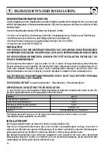
Install the voltage reducer in a dry and ventilated place.
The voltage reducer, although having high efficiency, develops a certain amount of heat during func-
tioning, therefore, it is imperative that the installation area has sufficient ventilation, enough to allow
use of the equipment at maximum power.
The voltage reducer can be installed in a horizontal or vertical position with cables coming out in the
downward position. The vertical position is recommended because the natural convection of heat
helps to cool the equipment.

CHARACTERISTICS AND INSTALLATION

GB

VRS SERIES VOLTAGE REDUCER

The long experience we have in the nautical field has given us the ability to develop the line of VRS voltage
reducer that guarantee higher performance when compared with other models currently on the market.
The advantages of the VRS voltage reducer are described below:

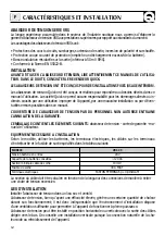
• Protection against shorts, overloads, output overvoltage, reverse polarity and overheating.
• Battery protection  (prevents the battery from being excessively discharged).
• Low residual output fluctuation (ripple lower than 50 mV RMS).
• Complies with EN 55022-B.

INSTALLATION

BEFORE USING THE VOLTAGE REDUCER CAREFULLY READ THIS USER’S MANUAL. IN CASE OF
DOUBT CONTACT THE “QUICK” SUPPLIER  OR AFTER SALES SERVICE DEPARTMENT.

THE VOLTAGE REDUCER HAS BEEN DESIGNED FOR FIXED INSTALLATIONS (FOR INDOOR USE
ONLY).

“Quick” voltage reducer have been designed and made for the reasons described in this user’s manual.
The “Quick” Company does not accept any responsibility for direct or indirect damage caused by
improper use of the equipment, bad installation or by possible errors occurring in this manual.

THE OPENING OF THE VOLTAGE REDUCER BY UNAUTHORISED PERSONNEL MAKES THE
WARRANTY VOID.

THE PACKAGE CONTAINS:

voltage reducer – warranty card – user’s manual.

EQUIPMENT NEEDED FOR INSTALLATION 

On the basis of the type of model, use the batteries, electrical terminals, and cables for the input/output
terminals and the output fuse as specified in the following table:

MODEL

Input battery voltage

Recommended battery capacity

Minimum output cable size

Output fuse 

Electric terminals

VRS 30

24 V

>120 Ah

10 mm

2

30 A FAST)

FASTON FEMMINA 6,3 x 0,8 ISOLATI

The required cable size is to be calculated according to the length of the conductors in order to avoid
excessive voltage drops.

8

Summary of Contents for VRS 30

Page 1: ...c a l e q u i p m e n t e v o l u t i o n Manuale d uso RIDUTTORI DI TENSIONE User s Manual VOLTAGE REDUCER Manuel de l utilisateur ABAISSEUR DE TENSION Benutzerhandbuch REDUZIERTRANSFORMATOR Manual d...

Page 2: ......

Page 3: ...llation Pag 13 Installation Branchements electriques de l appareil Pag 14 Fonctionnement Tableau de contr le Pag 15 Entretien Caract ristiques techniques SEITE 16 Eigenschaften und Installation SEITE...

Page 4: ...e a 50 mV RMS Conforme alla EN 55022 B INSTALLAZIONE PRIMA DI UTILIZZARE IL RIDUTTORE DI TENSIONE LEGGERE ATTENTAMENTE IL PRESENTE MA NUALE D USO IN CASO DI DUBBI CONTATTARE IL RIVENDITORE O IL SERVIZ...

Page 5: ...ONE prima di effettuare il collegamento alle batterie verificare attentamente la pola rit dei cavi provenienti dalla batteria Infatti un inversione di polarit potrebbe danneggiare seriamente il ridutt...

Page 6: ...a le cause che lo hanno ge nerato sono scomparse Per eliminare questa condizione necessario spegnere e riaccendere l ap parecchio PANNELLO DI CONTROLLO Nel pannello di controllo sono presenti due led...

Page 7: ...PROTEZIONI Tensione di alimentazione Assorbimento massimo CONTENITORE Materiale Dimensioni LxAxP Peso Inversione di polarit in ingresso Inversione di polarit in uscita Sovraccarico Cortocircuito in u...

Page 8: ...fluctuation ripple lower than 50 mV RMS Complies with EN 55022 B INSTALLATION BEFORE USING THE VOLTAGE REDUCER CAREFULLY READ THIS USER S MANUAL IN CASE OF DOUBT CONTACT THE QUICK SUPPLIER OR AFTER SA...

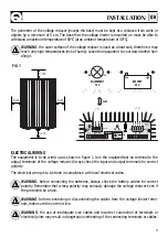
Page 9: ...ARNING before connecting the batteries always check the battery cables for correct polarity Remember that wrong polarity may seriously damage the voltage reducer even if the protected by a fuse WARNIN...

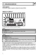
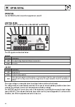
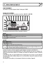
Page 10: ...en LED OUT This indicates that faults have arisen but they have disappeared To overcome the condition turn off the equipment and switch it back on CONTROL PANEL The control panel is made up of two LED...

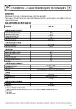
Page 11: ...mm 1 7 Kg INPUT CHARACTERISTICS PROTECTION Supply voltage Maximum absorption CASE Material Dimensions WxHxD Weight Reverse input polarity Reverse output polarity Overload Output short circuit Output o...

Page 12: ...mV RMS Conforme la Norme EN 55022 B INSTALLATION AVANT D UTILISER L ABAISSEUR DE TENSION LIRE ATTENTIVEMENT CE MANUEL DE L UTILISA TEUR DANS LE DOUTE CONSULTER LE REVENDEUR QUICK LES ABAISSEURS DE TE...

Page 13: ...NTION avant de raccorder les batteries contr ler attentivement la polarit des c bles qui proviennent de la batterie Une inversion de polarit pourrait endommager s rieusement l abaisseur de tension m m...

Page 14: ...ses qui l ont g n r ont disparu Pour liminer cette condition il est n cessaire d teindre et de rallumer l appareil TABLEAU DE CONTR LE Sur le tableau de contr le sont pr sentes deux Dels LED OUT et LE...

Page 15: ...7 Kg CARACTERISTIQUES D ENTREE PROTECTIONS Tension d alimentation Absorption maximum COFFRET Mat riaux Dimensions LxHxP Poids Inversion de polarit en entr e Inversion de polarit en sortie Surcharge C...

Page 16: ...Entspricht der Vorschrift EN 55022 B INSTALLATION VOR GEBRAUCH DES REDUZIERTRANSFORMATORS DAS VORLIEGENDE BENUTZERHANDBUCH AUFMERKSAM DURCHLESEN IM ZWEIFELSFALL DEN QUICK VERTRAGSH NDLER KONSULTIEREN...

Page 17: ...sgef hrt werden ACHTUNG Vor Anschluss der Batterien aufmerksam die Polung der von den Batterien kom menden Kabel kontrollieren Eine Verpolung kann das Ladeger t ernsthaft besch digen auch wenn es durc...

Page 18: ...ten ist aller dings sind die Ursachen die dieses erzeugt haben nicht mehr vorhanden Um diesen Zustand zu be heben muss das Ger t aus und dann wieder eingeschaltet werden BEDIENUNGS DISPLAY An der Steu...

Page 19: ...m 1 7 Kg EINGANGSEIGENSCHAFTEN SCHUTZEINRICHTUNGEN Verorgungsspannung Max Aufnahme BEH LTER Material Abmessungen LxHxT Gewicht Umpolung am Eingang Umpolung am Ausgang berlastung Kurzschluss am Ausgang...

Page 20: ...a 50 mV RMS Conforme a la EN 55022 B INSTALACI N ANTES DE UTILIZAR EL REDUCTOR DE TENSI N LEAN ATENTAMENTE EL PRESENTE MANUAL DEL USUARIO EN CASO DE DUDAS CONSULTEN CON EL DISTRIBUIDOR QUICK LOS REDUC...

Page 21: ...fectuar la conexi n de las bater as deber controlarse atentamente la polaridad de los cables provenientes de la bater a Recuerden que una inversi n de polaridad puede provocar graves da os al cargador...

Page 22: ...ero las causas que lo han ge nerado han desaparecido Para eliminar esta condici n es necesario apagar y volver a encender el equipo TABLERO DE CONTROL En el panel de control est n presentes dos leds L...

Page 23: ...TICAS DE ENTRADA PROTECCIONES Tensi n de alimentaci n Absorci n m xima RECIPIENTE Material Medidas LxAxP Peso Inversi n de polaridad en entrada Inversi n de polaridad en salida Sobrecarga Cortocircuit...

Page 24: ...189 254 169 3 OUT IN 24Vdc ON VRS 30 Green OK Red Error 13 5 Vdc POWER 68 173 6 3 VRS 30 DIMENSIONI mm DIMENSIONS DIMENSIONS ABMESSUNGEN MEDIDAS 24...

Page 25: ......

Page 26: ...NOTE NOTES NOTES DIE ANMERKUNGEN NOTAS...

Page 27: ......

Page 28: ...QUICK VIA PIANGIPANE 120 A 48020 PIANGIPANE RAVENNA ITALY TEL 39 0544 415061 FAX 39 0544 415047 www quickitaly com E mail quick quickitaly com CMVRGOOOOR01...

Reviews: