background image

17

GB

DYLAN DH 1500/1700/2000W  - REV001A

WARNING:

 before weighing anchor release the gypsy. 

Check that the control (32/33) that locks the gypsy is 
disengaged.

1) 

Release the gypsy safety lock (33). 

2) 

Have the gypsy lock control (32) slide toward the stern. 

3) 

Automatic inserting of the gypsy lock (31).

WARNING: 

stay clear of the chains, ropes and gypsy. Make sure the electric motor is off when windlass is used manually 

(even when using the handle to disengage the clutch). In fact people with windlass remote controls (hand-held remote 
control or radio-controlled systems) might accidentally operate it.

WARNING:

 secure the chain with a device before starting the navigation. 

WARNING:

 do not operate the windlass by using the electrical power when the handle is inserted in the drum or into the 

gypsy cover.

WARNING:

 Quick

®

 recommend using a circuit breaker designed for direct current (DC) with delayed-action (thermal-mag-

netic or hydraulic-magnetic) to protect the motor supply line from overheating or short circuits. The circuit breaker can be 
used to cut off power to the windlass control circuit and so avoid accidental activation.

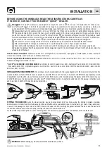
CLUTCH USE -

 The clutch (8 and 10) provides a link between the gypsy and the main shaft (19, 20, 21 or 22). The clutch can be 

released (disengagement) by using the handle (1) which, when inserted in the bush (7) of the drum or of the gypsy cover (2), 
must be turned counter-clockwise. The clutch will be re-engaged by turning it clockwise (engagement).


WEIGHING THE ANCHOR - 

Turn on the engine. Make sure the clutch is engaged and remove the handle. Press the UP button 

on the control provided. If the windlass stops and the hydraulic magnetic switch (or thermal cutout) has not tripped, wait a few 
seconds and try again (avoid keeping the button pressed). If the hydraulic magnetic switch, has tripped, reset it and wait a few 
minutes before weighing anchor once again. If, after a number of attempts, the windlass is still blocked, we suggest to move 
the boat to release the anchor. Check the upward movement of the chain for the last few meters in order to avoid damages to 
the bow. 

CASTING THE ANCHOR - 

The anchor can be cast by using the electrical control or manually. To operate manually, the clutch 

must be disengaged allowing the gypsy to revolve and letting the rope or chain fall into the water. To slow down the chain, the 
handle must be turned clockwise. To cast the anchor by using the electrical power, press the DOWN button on the control pro-
vided. In this manner, anchor casting is under control and the chain and rope unwind evenly. In order to avoid any stress on the 
windlass -once the boat is anchored- fasten the chain or secure it in place with a rope.

MANUAL ANCHOR WEIGHING (no drum version)

 Disconnect the windlass power supply. Use the lock lever control (32/33) to 

engage the lock lever (31) on the gypsy (9). Disengage the clutch (at least 2 turns of the bush anticlockwise), insert the lever (1) 
into the seat in the gypsy cover (4) and manually take up the chain by rotating the lever clockwise. After the manual weighing 
procedure remove the lever from its seat and insert it into the bush (2) to tighten the clutch. 

 Remove the lever (1) from the 

gypsy cover (4). Release the gypsy (9) using the control lever (32/33). Reconnect the windlass power supply. 

MANUAL ANCHOR WEIGHING (drum version) 

Disconnect the windlass power supply. Use the lock lever control (32/33) to en-

gage the lock lever (31) on the gypsy (9). Use the lever (1) to completely loosen the bush (7) and pull off the drum (6). Insert the 
lever (1) into the seat in the anchor weighing (45) and manually take up the chain by rotating the lever clockwise.
After the manual weighing procedure, remove the lever from its seat, reinsert the drum (6) and tighten the bush (7) to tighten 
the clutch. 

 Remove the lever (1) from the bush (7). Release the gypsy (9) using the control lever (32/33). Reconnect the 

windlass power supply.

DRUM USE

WARNING:

 Before carrying out warping operations, check that the anchor and relative rope or chain are solidly fixed to a 

bitt or another strong point on the boat. 

For the independent use of the drum (6), turn the lock lever control (32/33) to engage the lock lever (31) of the gypsy (9), release 
the clutch with the handle (1), (at least 2 turns of the bush anticlockwise). Remove the handle from the bush (7) on the gypsy, 
wrap the rope around the drum (at least 3 turns). Activate the windlass control, keeping the rope under tension during take up. 
By varying the tension during take up it is possible to modify the rope winding speed.

WARNING:


during take up maintain a safe distance between hands and windlass drum. 

Once take up is complete, screw up the clutch by tightening the gypsy drum clockwise and secure the rope to a bitt or other 
strong point on the boat.

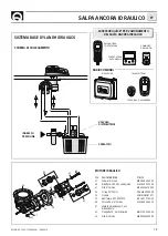
USAGE - WARNING

LOCK DISENGAGED

LOCK ENGAGED

1

2

3

33

32

31

Summary of Contents for DYLAN DH

Page 1: ...REV 001A High Quality Nautical Equipment Manuale d uso SALPA ANCORA VERTICALI User s Manual VERTICAL WINDLASSES DYLAN DH DH 1512 DH 1512 D DH 1712 DH 1712 D DH 1724 DH 1724 D DH 2024 DH 2024 D IT GB...

Page 2: ......

Page 3: ...importanti Pag 8 9 Schema di collegamento trifase Pag 10 11 Salpa ancora idraulico Pag 12 13 Manutenzione Pag 14 15 Set INDICE INDEX IT GB Pag 16 Technical data Pag 17 Installation Pag 18 Connection...

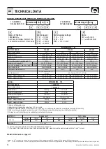
Page 4: ...na secondo il sistema Quick BARBOTIN 10 mm 3 8 12 13 mm Catena supportata 10 mm 10 mm 3 8 3 8 13 mm 12 mm 7 16 DIN 766 ISO G4 BBB DIN 766 ISO G4 Cima supportata 5 8 3 4 3 4 MODELLO DYLAN DH D POTENZA...

Page 5: ...c care la catena ad un punto fisso dell imbarcazione LA CONFEZIONE CONTIENE salpa ancora top motoriduttore cassetta teleruttori guarnizione della base dima di foratura leva viterie per l assemblaggio...

Page 6: ...lla pag 4 CASSETTA TELERUTTORI MOD T6315 12 12V MOD T6315 24 24V C A2 PULSANTI A PIEDE MOD 900U E 900D NERO MARRONE BLU MARRONE NERO BLU A1 FUSIBILE 4A 12V 2A 24V L L1 L2 L3 L4 L4 L2 L3 L1 L3 SCHEMA D...

Page 7: ...e la leva in senso orario Per calare l ancora elettricamente occorre premere il pulsante DOWN del comando a vostra disposizione In questo modo la calata perfettamente controllabile e lo svolgimento de...

Page 8: ...CHC1102 M CONTACATENA PER ANCORAGGIO MOD CHC1202 M DOWN UP BLU MARRONE NERO BLU MARRONE NERO DOWN SENSORE UP CAN H CAN L GRIGIO ROSSO VERDE MARRONE BIANCO BLU NERO BLU MARRONE NERO 150 CAN H CAN L CA...

Page 9: ...CONTACATENA A PULSANTIERA MOD CHC1102 M CONTACATENA PER ANCORAGGIO MOD CHC1202 M DOWN UP BLU MARRONE NERO BLU MARRONE NERO DOWN SENSORE UP CAN H CAN L GRIGIO ROSSO VERDE MARRONE BIANCO BLU NERO BLU MA...

Page 10: ...700W 41 39 38 40 37 36 6 7 75 15 12 2 3 4 8 10 13 14 28 27 25 29 31 30 32 33 34 18 16 19 21 5 5 5 5 5 9 11 35 42 23 23 23 23 20 22 17 16 1 24 26 50 51 52 53 54 55 56 49 48 47 46 70 44 45 46 43 44 45 7...

Page 11: ...morsetteria sup PCCPPMMR2000 68 Vite autofilettante M3 9x22 MBV03922AXCC 69 Vite autofilettante M3 9x32 MBV03932AXCC 70 Guarniz flangia ridut TOP TG60 PGFLRDTG6000 71 Guarniz flangia ridut TOP TG70 PG...

Page 12: ...leva viterie per l assemblaggio manuale di istruzioni condizioni di garanzia ATTREZZI NECESSARI PER L INSTALLAZIONE trapano con punta 12 mm 15 32 a tazza 90 mm 3 1 2 chiave esagonale 17 mm ACCESSORI...

Page 13: ...ILE PULSANTIERA RICEVITORE ACCESSORI QUICK PER L AZIONAMENTO DEL SALPA ANCORA IDRAULICO TRASMETTITORI RADIOCOMANDI POS DENOMINAZIONE CODICE 47 Grower 8 inox MBG08X000000 60 Riduttore 2000W serie Quick...

Page 14: ...rope with a rope chain splice manufactured with the Quick system GYPSY 10 mm 3 8 12 13 mm Chain size 10 mm 10 mm 3 8 3 8 13 mm 12 mm 7 16 DIN 766 ISO G4 BBB DIN 766 ISO G4 Rope size 5 8 3 4 3 4 MODEL...

Page 15: ...to a fixed point of the boat THE PACKAGE CONTAINS windlass on deck unit motorgearbox contactor unit base gasket drill template handle bolts and screws for assembly user s manual conditions of warranty...

Page 16: ...see table on page 12 CONTACTOR UNIT MOD T6315 12 12V MOD T6315 24 24V C A2 FOOT SWITCHES MOD 900U AND 900D BLACK BROWN BLUE BROWN BLACK BLUE A1 FUSE 4A 12V 2A 24V L L1 L2 L3 L4 L4 L2 L3 L1 L3 CONNECTI...

Page 17: ...the water To slow down the chain the handle must be turned clockwise To cast the anchor by using the electrical power press the DOWN button on the control pro vided In this manner anchor casting is un...

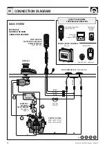
Page 18: ...ARD THREE PHASE CONNECTION DIAGRAM SENSOR WATERTIGHT HAND HELD CHAIN COUNTER MOD CHC1102 M WATERTIGHT PANEL CHAIN COUNTER MOD CHC1202 M DOWN UP BLUE BROWN BLACK BLUE BROWN BLACK DOWN SENSOR UP CAN H C...

Page 19: ...380V CA Max 5 5KW TERMINAL BOARD SENSOR WATERTIGHT HAND HELD CHAIN COUNTER MOD CHC1102 M WATERTIGHT PANEL CHAIN COUNTER MOD CHC1202 M DOWN UP BLUE BROWN BLACK BLUE BROWN BLACK DOWN SENSOR UP CAN H CAN...

Page 20: ...700W Provided in the box only in the version D 41 39 38 40 37 36 6 7 75 15 12 2 3 4 8 10 13 14 28 27 25 29 31 30 32 33 34 18 16 19 21 5 5 5 5 5 9 11 35 42 23 23 23 23 20 22 17 16 1 24 26 50 51 52 53 5...

Page 21: ...8 Self tapping screw M3 9x22 MBV03922AXCC 69 Self tapping screw M3 9x32 MBV03932AXCC 70 Gearbox flange gasket Top TG60 PGFLRDTG6000 71 Gearbox flange gasket Top TG70 PGFLRDTG7000 72 O ring bush PGR031...

Page 22: ...ons of warranty TOOLS REQUIRED FOR INSTALLATION drill and drill bits 12 mm 15 32 90 mm 3 1 2 hollow mill hexagonal wrenche 17 mm QUICK ACCESSORIES RECOMMENDED anchoring RL control board mod 800 Waterp...

Page 23: ...LD CHAIN COUNTER RECEIVER TRANSMITTERS REMOTE RADIO CONTROLS HANDHELD RADIO POCKET 62 78 81 82 47 83 82 79 80 60 47 61 POS DESCRIPTION CODE 47 Grower 8 stainless steel MBG08X000000 60 Gearbox 2000W Qu...

Page 24: ...INDLASSES CONTROL BOARD MOD 800 MOD 900 D DOWN FOOT SWITCH MOD 900 U UP L L1 L2 L3 L4 SENSOR MOTOR BATTERY c A2 A1 L4 L3 L2 DOWN UP BLUE BROWN BLACK BLUE BROWN BLACK DOWN SENSOR UP CAN H CAN L GREY RE...

Page 25: ...170 6 3 4 180 7 87 3 1 2 105 4 1 4 277 10 59 64 118 4 5 8 189 5 7 29 64 244 9 39 64 87 3 1 2 105 4 1 4 277 10 59 64 118 4 5 8 189 5 7 29 64 480 18 57 64 158 6 7 32 309 5 12 3 16 170 6 3 4 180 7 87 3...

Page 26: ...NOTE NOTES NOTES NOTIZEN NOTAS...

Page 27: ......

Page 28: ...ngipane 120 A 48124 Piangipane RAVENNA ITALY Tel 39 0544 415061 Fax 39 0544 415047 www quickitaly com E mail quick quickitaly com Codice e numero seriale del prodotto Product code and serial number GB...

Reviews: