background image


QUICK BGA EA-H00 OPERATION MANUAL                                                                                                     


Contents 

1. Summary .......................................................................................................................... 1


2. Product Picture ................................................................................................................. 2


3

Enchase component ........................................................................................................ 2


4. Safety Instructions ............................................................................................................ 2


5. Specifications and Technical Parameters ........................................................................... 3


5.1 Specifications ................................................................................................................. 3


5.2 Technical Parameters ...................................................................................................... 4


6. Install and Connect System ............................................................................................... 5


6.1 Place System .................................................................................................................. 5


6.2 Install RPC ..................................................................................................................... 5


6.3 System Connecting ......................................................................................................... 5


7. control box Instructions .................................................................................................... 6


8. IR System Operation ........................................................................................................ 6


8.1 Part Function .................................................................................................................. 6


8.2 Parameters Setting .......................................................................................................... 7


8.3 Operating technics instruction ....................................................................................... 15


9. PL System Operation ...................................................................................................... 18


9.1 Component function ..................................................................................................... 18


10

Equipment Maintenance ............................................................................................. 19


11

QUICKSOFT brief instruction ................................................................................... 20


11.1 operation interface ...................................................................................................... 20


11.2 parameter testing interface .......................................................................................... 21


11.3 curve analysis interface ............................................................................................... 22


11.4dvanced setting interface .............................................................................................. 22


Summary of Contents for BGA EA-H00

Page 1: ...ration Manual Thank you for purchasing our BGA SMD Rework System The system is exclusively designed for reworking and soldering SMD component Please carefully read this manual before operating the sys...

Page 2: ...5 6 1 Place System 5 6 2 Install RPC 5 6 3 System Connecting 5 7 control box Instructions 6 8 IR System Operation 6 8 1 Part Function 6 8 2 Parameters Setting 7 8 3 Operating technics instruction 15 9...

Page 3: ...lue of temperature for lead free soldering IR EA H00 Rework System adopts micro processor control and infrared sensor technology It has the precision non contact infrared temperature sensor for de sol...

Page 4: ...a RPC optional computer LCD optional Note The parts will be packed according to the packing list If you don t purchase the optional part it will not be in the package If any part stated above is misse...

Page 5: ...erators 5 Specifications and Technical Parameters 5 1 Specifications 1 Total power 2400W max 2 Power of Bottom Heater 400W 4 1600W Infrared ceramic heating tube 3 Power of Top Heater 120W 6 720W Infra...

Page 6: ...perature of top heater S1 Heating time rising from T1 to T2 S2 Heating time rising from T2 to T3 S3 Heat preservation time of T3 IR EA H00 Rework System has ten working modes and its parameter can be...

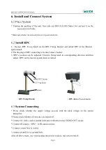
Page 7: ...be adjusted Unscrew fixing knob in corresponding direction and then adjust RPC can be moved up and down or turned 6 3 System Connecting Please check whether the supply voltage accords with the rated...

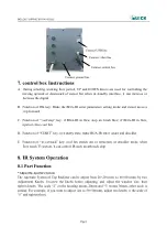
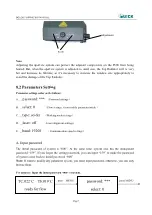
Page 8: ...te make BGA IR enter solder and desolder E Function of in out suck key cool fan stretch out or retraction in desolder mode when flow reach T3 section it can control IR suck mouth suck chip 8 IR System...

Page 9: ...0 Flow settings it can modify parameter inside C _type solder Working mode settings D _laser off Laser alignment settings E _baud 19200 Communication speed settings A Input password The initial passw...

Page 10: ...show 2 If you want to modify the next working flow operate as the following B item If you don t want to modify please press DOWN knob to browse the following parameter settings B Modify working flow...

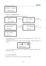
Page 11: ...modify the next working mode operate as C item shows If you don t want to modify it yon can press DOWN knob to browse the next parameter settings C Modify working mode For instance Modify the working...

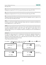
Page 12: ...e heat preservation starting temperature of reflow soldering It is the second temperature of this technics process The temperature rises to T1 with a proper speed the component permits In parameter mo...

Page 13: ...sed for measuring temperature besides system s IR sensor The signal of chosen sensor will be displayed and used for process controlling In parameter modifying use the UP and DOWN key to set the value...

Page 14: ...tate MENU press MENU press MENU rotate MENU press OK press MENU press MENU press MENU T1 130 S1 060s _T1 130 S1 060s T1 130 _S1 060s T1 130 S1 060s S1 070s T2 150 S1 070s T2 150 S1 060s T2 150 S1 060s...

Page 15: ...ress MENU press MENU MENU rotate MENU press OK rotate MENU rotate MENU rotate MENU press OK TL 183 TB 140 T0 090 T FAN 100S T FAN 100S SPD 80 T2 160 S2 030s T2 160 S2 050s T2 160 S2 050s S2 050s T3 20...

Page 16: ...Press OK key to exit Now the system has saved all parameter settings IR window will display 3 After all technology parameters have been selected press BEGIN key and the system perform the set flow E S...

Page 17: ...anical movement of machine until restart 2 When TC is less than 180 during working if the rising temperature is less than 7 and the system will exit the process and display TC raise error 3 If TC is o...

Page 18: ...rature of Tb and TC during working and indicate when it reaches T0 T1 T2 T3 and TL S1 S2 and S3 are counted down and user can know about the setting value clearly 7 If you see the solder has melted do...

Page 19: ...ng perform content of selected flow 7 After pressing START key Bottom Heater starts to heat up and Top Heater moves downwards and reach to bottom 8 IR window will show a series of setting temperatures...

Page 20: ...The other two Fixture Fixing Knobs are used for locking the PCB Fixture to prevent it from moving lengthways and transverse Unscrew PCB Fixing Knobs and move the Slide Block to open the PCB Clamp Bar...

Page 21: ...the equipment Solder on the glass of Bottom Radiator can be cleaned out with hard object Please be careful not to break down the glass Clean the prism of PL camera with pledget and be careful not to s...

Page 22: ...echnology flow file which parameter have be edit K type sensor KT1 KT3 only connect K type temperature sensor can display temperature Flow curve display window temperature curve of KT1 KT3 easy to rea...

Page 23: ...ght Suck height memory sucking height which have be set After setting auto memory this height when suck the same chip next time we can call the saved flow not need adjust counterpoint height Cancel su...

Page 24: ...re of this flow temperature rise slope temperature change of every heat process and time thus judge if correspond technology flow 2 In curve analysis interface can save or delete current curve or call...

Page 25: ...ftware and modify parameter If not set parameter protect password people who obtain enter password also modify parameter Language version select can select language china or English Select Chinese the...

Page 26: ...Changzhou Quick Soldering Co Ltd Add No 11 FengXiang Road Wujin High Tech Industrial Development Zone Jiangsu China Tel 86 519 86225678 Fax 86 519 86558599 Zip code 213167 Website www quick global com...

Reviews:

Related manuals for BGA EA-H00