background image

Chapter 2 Installation Guide

This section is to explain the cautions the users must know in some case that possible 

injure  may  bring  to  users  when  it’s  used  or  installed.  For  this  reason,  please  read  all 

details here and make in mind before installing or using the product. 

2.1 General Precautions 

Must be operated and maintained free of dust or dirty.

The cover should be securely fastened, do not open the cover of the products when the

power is on.

After use, securely stow away all loose cables, external antenna, and others.

2.2 Power precautions 

When you connect the power source, make sure if it may cause overload.

Avoid operating on a wet floor in the open. Make sure the extension cable is in good

condition

Make sure the power switch is off before you start to install the device

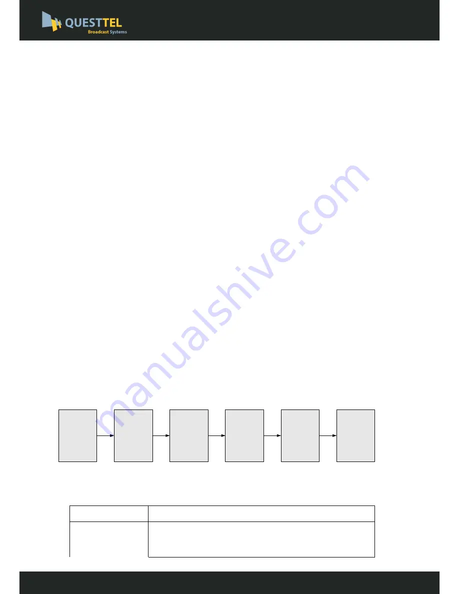
2.3 Device’s Installation Flow Chart Illustrated as following 

Connecting 

Grouding 

Wire and 

Power 

Cord

Acquisition 

Check

Installing 

Device

Setting 

Parameter

Running 

Device

Connecting 

Signal 

cable

2.4 Environment Requirement 

Item 

Requirement 

Machine 

Hall 

Space 

When  user  installs  machine  frame  array  in  one  machine  hall, 
the  distance  between  2  rows  of  machine  frames  should  be 
1.2~1.5m and the distance against wall should be no less than 

HDMI  MEPG-2  H.264  Encoder

 User Manual

B-HDMI-ASI-IP-2CH

www.questtel.com

[email protected]

Summary of Contents for B-HDMI-ASI-IP-2CH

Page 1: ...www questtel com sales questtel com User Manual 2CH HDMI to ASI and IP MPEG2 MPEG4 H 264 Encoder B HDMI ASI IP 2CH...

Page 2: ...contents of this document are subject to revision without notice due to continued progress in methodology design and manufacturing QuestTel shall have no liability for any error or damage of any kind...

Page 3: ...3 DEVICE S INSTALLATION FLOW CHART ILLUSTRATED AS FOLLOWING 5 2 4 ENVIRONMENT REQUIREMENT 5 2 5 GROUNDING REQUIREMENT 6 CHAPTER 3 OPERATION 7 3 1 LCD MENU CLASS TREE 7 3 2 INITIAL STATUS 8 3 3 GENERA...

Page 4: ...structural design which greatly facilitates the change of encoding modules to SDI if needed 1 2 Key Features Dual power supply MPEG2 HD SD MPEG4 AVC H 264 HD SD video encoding MPEG1 Audio Layer 2 LC...

Page 5: ...Layer II MPEG2 AAC MPEG4 AAC Dolby Digital AC3 Sample rate 48KHz Bit rate 64kbps 96kbps 128kbps 192kbps 256kbps 320kbps System Local interface LCD control buttons Remote management Web NMS Low Latenc...

Page 6: ...one power supply is connected or one of the power supplies fails the device will give alarm sound and then press the alarm switch to turn off the alarm sound NMS port for the connection between the d...

Page 7: ...Input Module 1 Program input port 1 HDMI Input Module 2 Program input port 2 ASI output ports Power Supply Slot Power Switch Grounding HDMI MEPG 2 H 264 Encoder User Manual B HDMI ASI IP 2CH www ques...

Page 8: ...nnect the power source make sure if it may cause overload Avoid operating on a wet floor in the open Make sure the extension cable is in good condition Make sure the power switch is off before you sta...

Page 9: ...other Device power requires AC 110V 10 50 60Hz or AC 220V 10 50 60Hz Please carefully check before running 2 5 Grounding Requirement All function modules good grounding is the basis of reliability and...

Page 10: ...h Audio Gain Service name Program name Program number PCR PID Video PID Program output PMT PID Audio PID 4 Network 4 1 NMS 4 2 IP Stream 4 1 1 NMS IP 4 1 2 Subnet mask 4 1 3 Gateway 4 1 4 MAC Address...

Page 11: ...owing pages where user can configure the parameters for the device User can press UP DOWN buttons to specify one item and then press ENTER to enter its submenus Press MENU to step back to upper level...

Page 12: ...1 or 2 2 user could set the video audio parameters for the 2 HDMI programs respectively 2 1 Input 1 2 2 Input 2 2 1 1 Program 1 2 1 2 Program 2 Uptime 0 Day s xx xx xx Video Video in status Video For...

Page 13: ...chieve a low time delay from encoding to decoding terminal end to end NOTE The different combination of Video Format Video Bit rate Low Delay Mode the Resolution of signal source and Decoding solution...

Page 14: ...Gain Users can adjust the audio gain in this menu Program Info Users can enable or disable the program output in the first sub menu and configure the other parameters in the rest sub menus EIA 608 EIA...

Page 15: ...n the 2 submenus The IDs are in hexadecimal form Output Bit rate Users can set the max output bit rate for the ASI MPTS out Range 0 100 Mbps PMT PID 0x101 PCR PID 0x100 Video PID 0x100 Audio PID 0x100...

Page 16: ...setting the parameters related to the device connection in the network 4 1 NMS 4 2 IP Stream Output Bit rate 60 000 Mbps NIT Insert Yes No ASI Output MPTS NMS 4 1 1 NMS IP 4 1 2 Subnet Mask 4 1 3 Gat...

Page 17: ...ding parameters Data Enable Null PKT Filter Output IP Output Port Service IP Subnet Mask Gateway 192 168 000 001 MAC Address 201012345678 Reset Password Yes NO Web NMS Port 00080 IP Stream 4 2 1 MPTS...

Page 18: ...last saved configuration Choose yes to restore the device into factory s default configuration Press DOWN UP key to select a time out for the LCD lighting duration 5 120 seconds It displays the devic...

Page 19: ...and the device with net cable and use ping command to confirm they are on the same network segment I G the PC IP address is 192 168 99 252 we then change the device IP to 192 168 99 xxx xxx can be 1...

Page 20: ...oding module as Figure 3 It automatically identifies and displays the signal source interface and real time encoding bit rate of corresponding input channel User can click any item here to enter the c...

Page 21: ...ace Click this button to apply the default setting of Input 1 Click this button to apply the modified parameters This column is for setting the 1st SDI IN program This column is for setting the 2ed HD...

Page 22: ...he parameters click Apply to save the setting General Clicking General from the menu it will display the interface as Figure 5 where to set the network info for the output TS This device supports 1 MP...

Page 23: ...estart the Device Click Reboot from the menu the screen will display as Figure 7 Here when clicking Reboot box it will restart the device automatically Users can copy a stream from the IP out streams...

Page 24: ...then click Update to update the device After updating the device user needs to restart the device by using Reboot option Figure 8 Network When user clicks Network it will display the screen as Figure...

Page 25: ...ce Figure 10 Keyboard and LCD Lock If it is marked with the LCD and keyboard will be locked to avoid unrelated users modifying or view the device information and configurations User can t operate the...

Page 26: ...Load Configuration If user needs to load the old configuration to the device click Browse and find the backup configuration file path After selecting the file click Load File to load the backup file...

Page 27: ...nge if it is necessary Checking all signal cables have been properly connected Frequently switching on off device is prohibited the interval between every switching on off must greater than 10 seconds...

Page 28: ...Chapter 6 Packing List 1PC 1PC 2PCs B HDMI ASI IP 2CH Encoder User Manual HDMI Cables Power Cord 1PC HDMI MEPG 2 H 264 Encoder User Manual B HDMI ASI IP 2CH www questtel com sales questtel com...

Reviews: