background image

1-866-413-5214 

Quest Gas Fired CHH-300 Installation, Operation and Maintenance Instructions


3

quest

quest

www.QuestOnTheJob.com

[email protected]


This appliance is equipped with a Blocked-Flue shutoff device. If any part of the flue-gas 
passageway in the combustion chamber, exhaust pipe or rain cap should become blocked or 
adversely restricted, a pressure sensing switch (Fig.22 pg.12) will break the electrical control circuit 
and not allow the burner to run or the gas valve to open. There is a “Manual Reset” button on this 
switch that will have to be reset before re-firing can occur. If the burner fails to start after resetting 
once, call a qualified service technician to clean the flue passageways and/or replace the switch. 
Cleaning instructions can be found in Section (6.1 G) of the Maintenance section of this manual.

Summary of Contents for CHH-300

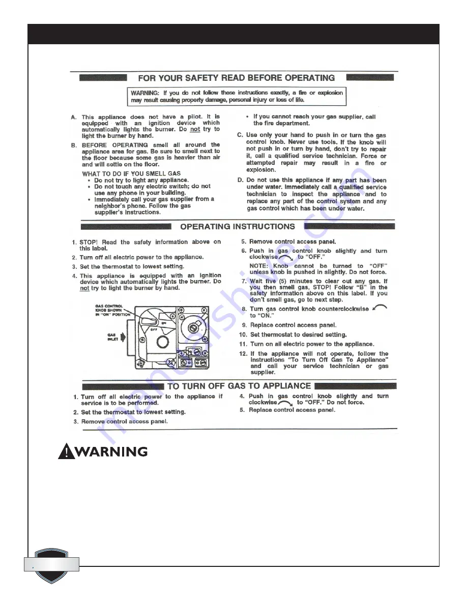
Page 1: ...death Do NOT store or use gasoline or other flammable vapors and liquids in the vicinity of this or any other appliance WHAT TO DO IF YOU SMELL GAS Do NOT try to light any appliance Do NOT touch any electrical switch do not use any phone in your building Immediately call your gas supplier from a neighbor s phone Follow the gas supplier s instructions If you cannot reach your gas supplier call the ...

Page 2: ...quest quest 1 866 413 5214 Quest Gas Fired CHH 300 Installation Operation and Maintenance Instructions 2 www QuestOnTheJob com sales QuestOnTheJob com ...

Page 3: ...become blocked or adversely restricted a pressure sensing switch Fig 22 pg 12 will break the electrical control circuit and not allow the burner to run or the gas valve to open There is a Manual Reset button on this switch that will have to be reset before re firing can occur If the burner fails to start after resetting once call a qualified service technician to clean the flue passageways and or ...

Page 4: ...cal Requirements for Complete System 10 3 7 Gauges Indicator Lights 11 3 8 Controls Electrical 11 3 9 Controls Switches Gauges Identification 13 4 Setup 14 4 1 Positioning Equipment on the job 14 4 2 Hose Accessory Connections 14 4 3 Charging the Fluid System 16 4 4 Propane Gas Burner Installation Setup 17 4 5 Natural Gas Burner Installation Setup 18 5 Operation 18 5 1 Startup 18 5 2 Shutdown 19 6...

Page 5: ...e with dependent heat exchangers such as Fan coils for heating and drying of structures Multi circuit line heat exchange hose or tubing for ground thawing concrete curing snow melting and slab heating Custom hydronic heat exchange accessories and applications The CHH gas fired units can be equipped with either of 2 burners each dedicated to burn one of the following Natural Gas Propane Gas Pumping...

Page 6: ...ator even when the system is securely locked down Burners approved for use with the system come with a permanently installed pressure gauge to simplify adjustment of gas pressure when setting up the burner Door handles and hose connection couplers for the external HTF circuit are recessed so as not to create snag points when moving shipping or delivering the unit 2 Safety 2 1 General Safety Guidel...

Page 7: ...ion should be sufficient for most conditions Respiratory protection No respiratory protection should be needed Skin protection For brief contact no precautions other than clean body covering clothing should be needed Use impervious gloves when prolonged or frequently repeated contact should occur Eye protection Use safety glasses First aid measures Eyes Flush eyes with plenty of water Skin Wash of...

Page 8: ... The Gas Burner is a power forced draft type with direct spark ignition manufactured by Riello Burners A CSA UL version gas train is factory installed in units equipped for either propane or natural gas The gas train works with either burner Two gauges are mounted to pressure tap ports on the gas train for use in setting the burner and monitoring performance Fig 24 Length of Cabinet inches millime...

Page 9: ... stainless steel direct drive centrifugal type The pump is located inside the enclosure at the opposite end to the burner and can be accessed through a hinged lockable door Fig 1 A panel mounted pressure gauge is connected to the output side of the HTF pump by means of a 1 8 ID hydraulic hose and fittings Fig 23 3 Gas Burner LP or Natural Gas Train Riello Burner Model Natural Gas 40 G400 NG Operat...

Page 10: ...60 Phase PH single Control Circuit Voltage Volts 120 Power Inlet NEMA Twistlock L5 20P 5 Power Inlet Plug 4 Fluid circulation Pump Goulds Pump Model 1ST1E4C4 Impeller Diameter inches millimeters 5 1875 132 Motor Horsepower HP Watts 1 0 746 Voltages pump can run on Volts 120 240 Full Load Amp Rating Franklin motor Amps 10 4 5 2 Emerson motor Amps 12 3 6 2 System Design Flow Rate USGPM liters sec 30...

Page 11: ... in sequence as each of the following scenarios is proven 1 115 volt control power is present clear lens 2 HTF level is adequate in reservoir green lens 3 High temp auto switch has not interrupted the circuit green lens 4 High temp limit control has not interrupted the circuit green lens 5 High pressure switch has not interrupted the circuit green lens 6 Aquastat is calling for heat green lens 3 8...

Page 12: ...nal blocks Fig 18 Contactors Fig 17 Electronic operating thermostat Fig 8 The following items are remotely connected to cords that exit from the control panel see chart below for details of these components Main power male inlet plug twist lock Fig 5 Low water cut off switch mounted on HTF reservoir Fig 19 High Temp Auto switch mounted in HTF plumbing circuit Fig 20 High Temp Limit switch mounted ...

Page 13: ...ator Digital 9 Main Power Switch Knob 10 Pump Switch 11 Burner Switch 12 Temperature Gauges Hour Meter 13 LED Indicator Lights 3 9 Controls Switches Gauges Identification Mounted on Control Panel Mounted Behind Control Panel Mounted Remotely 14 Circuit Breakers 15 Main Power Switch Body 16 Transformers for Digital Temp Gauges 17 Contactors 18 Terminal Blocks ...

Page 14: ... 20A 3 wire grounding is required Convenient access to bulk truck re fueling in the case of propane systems Do not locate in the path of job site traffic Avoid locations that will expose the CHH to intense dust or other sources of air contamination Clean flowing air is essential to maintain clean combustion Observe all requirements listed in the Instructions for Installation document provided with...

Page 15: ...of the hose circuit Route hoses to achieve minimum chance of damage from traffic of any kind and at the same time minimize the overall circuit length Provide protection from Kinking of hoses that would restrict flow When connecting quick couplers ensure that the connections are Fully Engaged and snapped into place or flow will not take place through the coupler connection For long term building he...

Page 16: ...fluid is a 50 blend of Inhibited propylene glycol and de mineralized neutral PH 7 water Freeze protection to 29ºF The HTF provided with a new system and accessories is marketed as DowFrost Use of any other product that cannot be proven to be equal in all respects will void warranty of the system 26 Hoses Connected to CHH Unit 27 Fancoil Connected to CHH Unit 28 Manifolds for Fancoils Supply Return...

Page 17: ... circuit Air has been purged when steady pressure of 30 to 35 PSI is observed at the glycol pressure gauge Fig 22 Connect each fancoil or thaw cure loop in turn one at a time in the same manner as above When all are connected and the pressure gauge maintains steady pressure the system is charged and ready for use Check the HTF level again and top up if necessary to full 4 4 Propane Burner Installa...

Page 18: ... come on as well as the two digital temperature gauges and hour meter Fig 12 Turn ON the pump switch Fig 10 and check the pump pressure gauge Fig 22 Steady pressure around 30 to 35 PSI indicates that no air remains in the fluid circuit Once a stable pump pressure is achieved turn ON the burner switch Fig 11 The following sequence should now occur Observe the LED light cluster Fig 13 The glycol lev...

Page 19: ...300 Fig 26 This will prevent fluid from draining back and overflowing at the HTF reservoir vent Fig 30 Turn OFF the main power switch Fig 9 Turn OFF manual gas supply valves If the system is to be de commissioned it is now safe to disconnect the power supply the natural gas or propane supply if applicable and all HTF circulation hoses manifolds and accessories 6 Maintenance 6 1 Service Instruction...

Page 20: ... open the burner circuit to prevent burner initiation b By pushing the reset switch the control will restore function to the burner circuit as long as there is fluid touching the probe The electronic probe is a self cleaning type and should not require service c This control should be tested every time when putting the system into operation on a new project or a minimum of once yearly E After plac...

Page 21: ...amber The following steps should be taken to clean out the chamber flue gas passageway Must be performed by a trained service technician ONLY a Shut off and disconnect external gas supply and electrical power supply b Drain the heat transfer fluid from the system c Exterior cabinet side panels and the cabinet door framing members at the burner end of the cabinet should be removed to facilitate acc...

Page 22: ...ue to be kept clear and free from combustible materials gasoline and all other flammable vapors and liquids K At the circulation pump end of the CHH 300 cabinet Louvers are stamped into the access door to provide intake air for combustion and ventilation Check on a daily basis to ensure that nothing is allowed to obstruct this free flow of air L Check heat transfer fluid level daily Maintain betwe...

Page 23: ...enance Frequency Chart 7 Troubleshooting 7 1 Fault Determination The CHH 300 is equipped with a group of LED Indicator Lights The purpose of these lights is to aid in determining where the fault lies if the heating unit should fail to function properly The following sequence explains the function each light represents and what to look for if that function fails ...

Page 24: ... LWCO should be energized 120V This opens contacts in a relay that will prevent the pump from running with no fluid in the system 2 LWCO Light plus 1 are ON indicates A LWCO switch Fig 19 is sensing sufficient glycol in the reservoir and power is going through the switch B There is no power going through the high temperature auto switch Fig 20 a Check the set points on the high temperature auto sw...

Page 25: ...volts going in and out of the control If power goes in but not out replace the control c If the circuit is restored briefly but it trips again blockage may have occurred in the flue gas passage way Clean the flue gas passages in the combustion chamber see Maintenance article 6 1 G for instructions as well as the chimney pipe and rain cap Repeat step a above 5 High Pressure Switch Light plus 1 2 3 ...

Page 26: ...s c The spark is irregular or not present C The burner does not start when the thermostat calls for heat a The 24 volt switching relay is defective b Terminals on the control module are bent or loose c The motor is defective d The capacitor is defective e The control box is defective f The air pressure switch is not in the normally closed position D The burner does not go through prepurge and the ...

Page 27: ...1 866 413 5214 Quest Gas Fired CHH 300 Installation Operation and Maintenance Instructions 27 quest quest www QuestOnTheJob com sales QuestOnTheJob com ...

Page 28: ...quest quest 1 866 413 5214 Quest Gas Fired CHH 300 Installation Operation and Maintenance Instructions 28 www QuestOnTheJob com sales QuestOnTheJob com Riello Burner Wiring ...

Page 29: ...unauthorized or improper repair or installation accident acts of nature or any other cause beyond Therma Stor LLC reasonable control Limitations and Exclusions If any Quest CHH 300 part is repaired or replaced the new part shall be warranted for only the remainder of the original warranty period applicable thereto but all warranty periods will be extended by the period of time if any that the Ques...

Reviews: