


UMTS/HSPA Module Series
UC20 Hardware Design
UC20_Hardware_Design Confidential / Released 43 / 84
Some AT commands are invalid when USIM card is not applied.
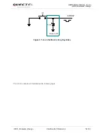
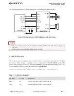
UC20 supports USIM card hot-plugging via the USIM_PRESENCE pin. For details, refer to
document [1]
about the command
AT+QSIMDET
. If you do not need the USIM card detection function, keep
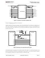
USIM_PRESENCE unconnected. The reference circuit for using a 6-pin USIM card connector is
illustrated as the following figure.
Module
USIM_VDD
USIM_GND
USIM_RST
USIM_CLK
USIM_DATA
22R
22R
22R
100nF
USIM Connector
GND
ESDA6V8AV6
33pF 33pF 33pF
VCC
RST
CLK
IO
VPP
GND
GND
15K
USIM_VDD
Figure 23: Reference Circuit of the 6 Pin USIM Card
In order to enhance the reliability and availability of the USIM card in your application, please follow the
following criterion in the USIM circuit design:
Keep layout of USIM card as close as possible to the module. Assure the length of the trace is less
than 200mm.
Keep USIM card signal away from RF and VBAT alignment.
Assure the ground between module and USIM connector short and wide. Keep the width of ground
and USIM_VDD no less than 0.5mm to maintain the same electric potential. The decouple capacitor
of USIM_VDD should be less than 1uF and must be near to USIM connector.
To avoid cross-talk between USIM_DATA and USIM_CLK, keep them away with each other and
shield them with surrounded ground.
In order to offer good ESD protection, it is recommended to add TVS such as WILL
(http://www.willsemi.com) ESDA6V8AV6. The 22Ω resistors should be added in series between the
module and the USIM card so as to suppress the EMI spurious transmission and enhance the ESD
protection.
The pull-up resistor on USIM_DATA line can improve anti-jamming capability when long layout trace
and sensitive occasion is applied.
NOTE