Smart Wi-Fi Module Series
SC20-WL Hardware Design
SC20-WL_Hardware_Design
47 / 81
VIB_DRV
1
4
3V3
Module
VIB+
Motor
VIB-
1uF
NM
D1
C1
C2
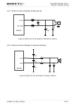
Figure 18: Reference Circuit for Motor Connection
When the motor stops, the redundant electricity can be discharged from the circuit loop formed by diodes,
thus avoiding component damages.
3.17. LCM Interface
SC20-WL module provides an LCM interface meeting MIPI DSI specification. The interface supports high
speed differential data transmission, with up to four lanes and a transmission rate up to 1.5Gbps per lane.
It supports maximally 720P resolution displays.
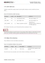
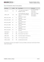
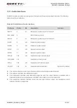
Table 16: Pin Definition of LCM Interface
Pin Name
Pin No
I/O
Description
Comment
LDO6_1V8
125
PO
1.8V output power supply for
LCM logic circuit and DSI
1.8V normal voltage.
Vnorm=1.8V
I
O
max=100mA
LDO17_2V85
129
PO
2.85V output power supply for
LCM analog circuits
2.85V normal voltage.
Vnorm=2.85V
I
O
max=300mA
PWM
29
DO
Adjust the backlight brightness.
PWM control signal.
LCD_RST
49
DO
LCD reset signal
Active low
LCD_TE
50
DI
LCD tearing effect signal


