5G Module Series
RM505Q-AE Hardware Design
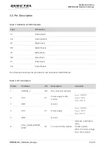
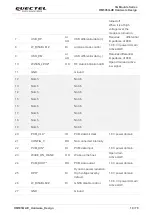
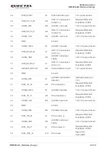
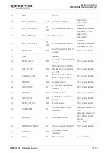
RM505Q-AE_Hardware_Design 32 / 79
Module
(U)SIM Card
Connector
USIM_DET
USIM_DATA
USIM_CLK
RST
CLK
CD1
IO
USIM_VDD
USIM_VDD
USIM_RST
VCC
GND
VPP
GND
TVS
Note:
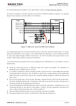
All these resistors, capacitors and TVS should be close to (U)SIM card connector in PCB layout.
10-20k
22R
22R
22R
3
3
p
F
3
3
p
F
3
3
p
F
100 nF
33k
1.8 V
4.7k
CD2
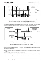
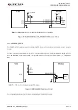
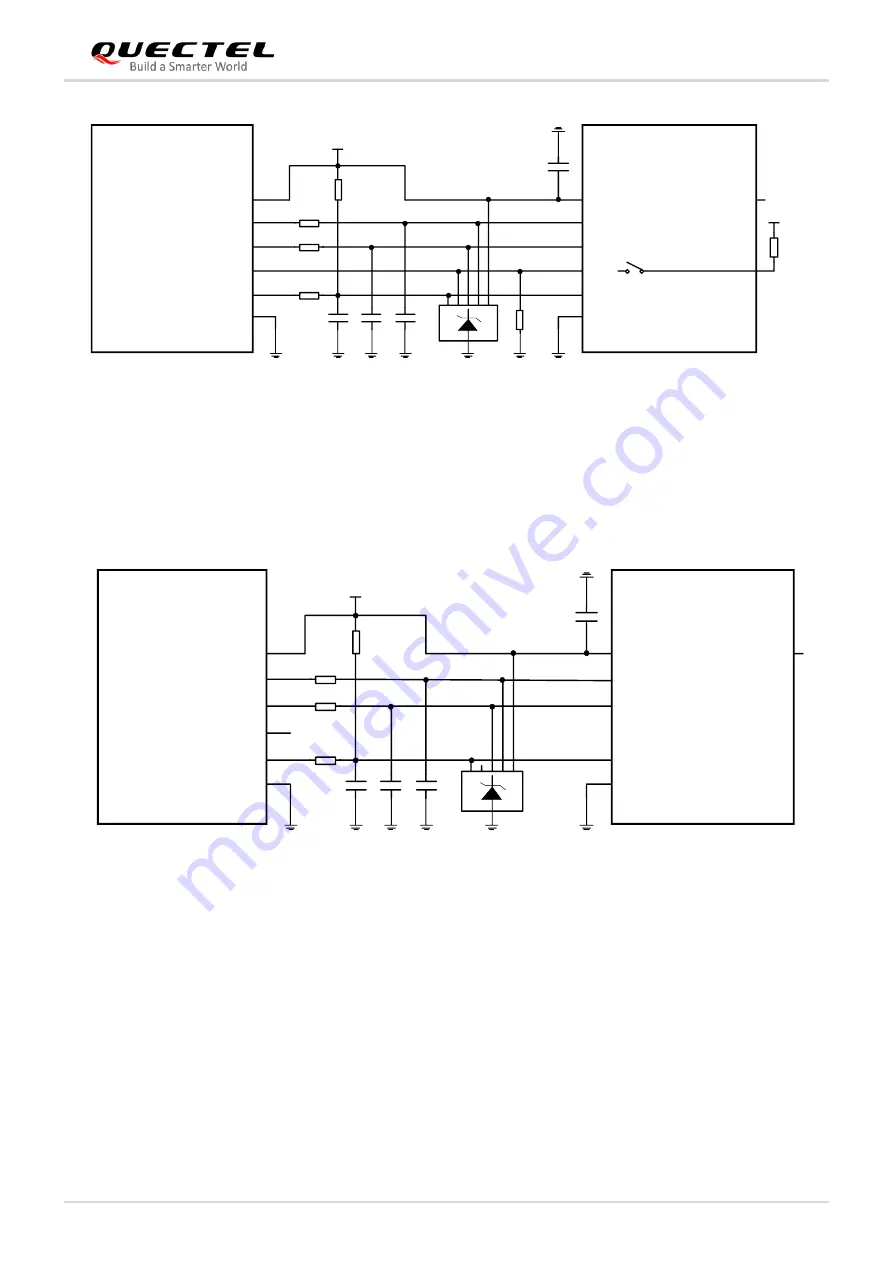
Figure 15: Reference Circuit for Normally Open (U)SIM Card Connector
If (U)SIM card detection function is not needed, please keep USIM_DET disconnected. A reference circuit
for (U)SIM card interface with a 6-pin (U)SIM card connector is illustrated by the following figure.
Module
(U)SIM Card
Connector
USIM_DET
USIM_DATA
USIM_CLK
RST
CLK
IO
USIM_VDD
USIM_VDD
USIM_RST
VCC
GND
VPP
GND
TVS
Note:
All these resistors, capacitors and TVS should be close to (U)SIM card connector in PCB layout.
10-20k
22R
22R
22R
3
3
p
F
3
3
p
F
3
3
p
F
100 nF
Figure 16: Reference Circuit for a 6-Pin (U)SIM Card Connector
To enhance the reliability and availability of the (U)SIM card in applications, please follow the criteria
below in (U)SIM circuit design.
⚫
Place the (U)SIM card connector as close to the module as possible. Keep the trace length less than
200 mm.
⚫
Keep (U)SIM card signals away from RF and VCC traces.
⚫
Make sure the ground between the module and the (U)SIM card connector is short and wide. Keep
the trace width of ground and USIM_VDD no less than 0.5 mm to maintain the same electric

