5G Module Series
RG255C-GL_Mini_PCIe_Hardware_Design 47 / 57
still work but the performance and function (such as RF output power, data rate) will be affected to a
certain extent. Therefore, the thermal design should be maximally optimized to ensure all internal IC chips
always work within the recommended operating temperature range.
The following principles for thermal consideration are provided for reference:
⚫
Keep the module away from heat sources on your PCB, especially high-power components such as
processor, power amplifier, and power supply.
⚫
Maintain the integrity of the PCB copper layer and drill as many thermal vias as possible.
⚫
Expose the copper in the PCB area where module is mounted.
⚫
Apply a soft thermal pad with appropriate thickness and high thermal conductivity between the
module and the PCB to conduct heat.
⚫
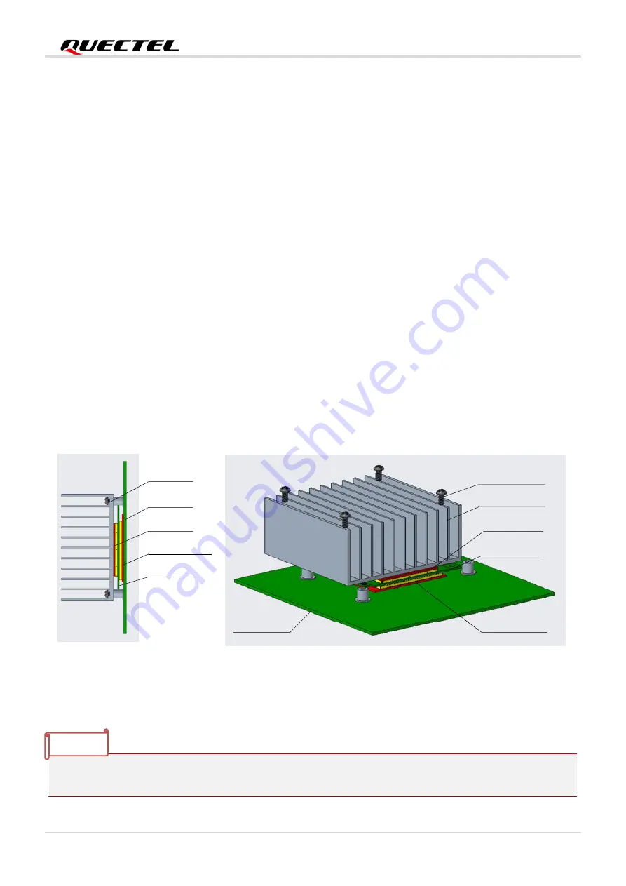
Follow the principles below when the heatsink is necessary:
-
Do not place large size components in the area where the module is mounted on your PCB to
reserve enough place for heatsink installation.
-
Attach the heatsink to the shielding cover of the module; In general, the base plate area of the
heatsink should be larger than the module area to cover the module completely;
-
Choose the heatsink with adequate fins to dissipate heat;
-
Choose a TIM (Thermal Interface Material) with high thermal conductivity, good softness and
good wettability and place it between the heatsink and the module;
-
Fasten the heatsink with four screws to ensure that it is in close contact with the module to
prevent the heatsink from falling off during the drop, vibration test, or transportation.
Heatsink
PCB
TIM
Thermal pad
Module
Thermal pad
Module
TIM
Heatsink
Screw
PCB
Figure 20: Placement and Fixing of the Heatsink
The module offers the best performance when the internal BB chip stays below 95 °C. When the
maximum temperature of the BB chip reaches or exceeds 95 °C, the module works normal but provides
NOTE


