GSM/GPRS/GNSS Module Series
MC60 Series Hardware Design
MC60_Series_Hardware_Design Confidential / Released 36 / 114
If the GSM part is set to minimum functionality by
AT+CFUN=0
, the RF function and (U)SIM card function
would be disabled. In this case, the UART port is still accessible, but all AT commands related with RF
function or (U)SIM card function will be unavailable.
If the GSM part is set by the command
AT+CFUN=4
, the RF function will be disabled, but the UART port
is still active. In this case, all AT commands related with RF function will be unavailable.
After the GSM part is set by
AT+CFUN=0
or
AT+CFUN=4
, it can return to full functionality mode by
AT+CFUN=1
.
For detailed information about
AT+CFUN
, please refer to
document [1]
.
3.6.1.2. Sleep Mode
Sleep mode is disabled by default. It can be enabled by
AT+QSCLK=1
. The default setting is
AT+QSCLK=0
, and in this mode, the GSM part cannot enter Sleep mode.
When the GSM part is set by the command
AT+QSCLK=1
, customers can control the part to enter into or
exit from the Sleep mode through pin DTR. When DTR is set to high level, and there is no on-air or
hardware interrupt such as GPIO interrupt or data on UART port, the GSM part will enter into Sleep mode
automatically. In this mode, the GSM part can still receive voice, SMS or GPRS paging from network, but
the UART port does not work.
3.6.1.3. Wake up GSM Part from Sleep Mode
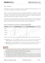
When the GSM part is in the Sleep mode, it can be woken up through the following methods:
If the DTR pin is set low, it would wake up the GSM part from the Sleep mode. The UART port will be
active within 20ms after DTR is changed to low level.
Receiving a voice or data call from network wakes up the GSM part.
Receiving an SMS from network wakes up the GSM part.
DTR pin should be held at low level during communication between the GSM part and the DTE.
NOTE
Quectel
Confidential


