background image


GNSS  Module  Series 

                                                                                                                                L89  EVB  User  Guide 

L89_EVB_User_Guide                                                                                                                                17 / 26 


4.2. Firmware Downloading 


L89 module supports the firmware downloading in both normal working mode and boot download mode 

by using the tools of STA808x/9x Firmware Upgrade and TeseoIII XLoader respectively. 


4.2.1.  Firmware Downloading in Normal Working Mode 

Steps of firmware downloading in normal working mode are as follows: 


Step 1:

  Connect the EVB to a PC by using the USB cable. 


Step 2: 

Switch the POWER pin to ON state to power on the EVB. 


Step 3:

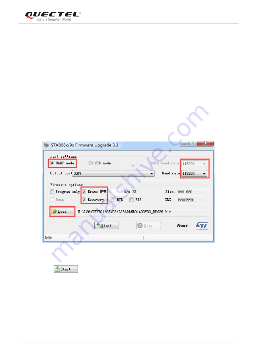
  Run the STA808x/9x Firmware Upgrade Tool and configure the tool as shown below. 


Figure 11: STA808x/9x Firmware Upgrade Tool Configurations for Firmware Upgrade 


Step 4:

  Click                        button and then reset the module to upgrade the firmware. 


Summary of Contents for L89 EVB

Page 1: ...L89 EVB User Guide GNSS Module Series Rev L89_EVB_User_Guide_V1 0 Date 2019 12 10 Status Released www quectel com ...

Page 2: ...INFORMATION PROVIDED IS BASED UPON CUSTOMERS REQUIREMENTS QUECTEL MAKES EVERY EFFORT TO ENSURE THE QUALITY OF THE INFORMATION IT MAKES AVAILABLE QUECTEL DOES NOT MAKE ANY WARRANTY AS TO THE INFORMATION CONTAINED HEREIN AND DOES NOT ACCEPT ANY LIABILITY FOR ANY INJURY LOSS OR DAMAGE OF ANY KIND INCURRED BY USE OF OR RELIANCE UPON THE INFORMATION ALL INFORMATION SUPPLIED HEREIN IS SUBJECT TO CHANGE ...

Page 3: ...GNSS Module Series L89 EVB User Guide L89_EVB_User_Guide 2 26 About the document Revision History Revision Date Author Description 1 0 2019 12 10 Gobber HU Initial ...

Page 4: ...cation LEDs 13 3 5 Test Points 14 4 EVB Operation Procedures 15 4 1 Communication through Micro USB Interface 15 4 2 Firmware Downloading 17 4 2 1 Firmware Downloading in Normal Working Mode 17 4 2 2 Firmware Downloading in Boot Download Mode 18 5 Usage of Teseo Suite Pro Tool 19 5 1 View GNSS Receiver Status 19 5 1 1 COM Port and Baud Rate Setting 19 5 1 2 Explanations of Views and Windows 21 5 2...

Page 5: ... Table Index TABLE 1 INTERFACES OF L89 EVB 8 TABLE 2 KEY FEATURES OF L89 EVB 8 TABLE 3 LIST OF ACCESSORIES 9 TABLE 4 L89 EVB SWITCHES AND BUTTONS 13 TABLE 5 OPERATION STATUS INDICATION LEDS 13 TABLE 6 PIN DESCRIPTION OF J106 14 TABLE 7 TERMS AND ABBREVIATIONS 26 ...

Page 6: ... FIGURE 10 COM PORT SETTING INTERFACE OF QCOM 16 FIGURE 11 STA808X 9X FIRMWARE UPGRADE TOOL CONFIGURATIONS FOR FIRMWARE UPGRADE 17 FIGURE 12 TESEOIII XLOADER TOOL CONFIGURATIONS FOR FIRMWARE UPGRADE 18 FIGURE 13 TESEO SUITE PRO TOOL INTERFACE 19 FIGURE 14 MANUAL CONFIGURATION OF THE COM PORT 20 FIGURE 15 SIGNAL LEVEL 21 FIGURE 16 SKY VIEW 22 FIGURE 17 MODULE POSITIONING FORM 22 FIGURE 18 COMMAND S...

Page 7: ...s into all manuals supplied with the product If not so Quectel assumes no liability for customers failure to comply with these precautions Ensure the use of the product conforms to the local safety and environment regulations and is allowed in the country and the environment required Keep away from explosive and flammable materials The use of electronic products in extreme power supply conditions ...

Page 8: ...GNSS Module Series L89 EVB User Guide L89_EVB_User_Guide 7 26 2 General Overview 2 1 Top View The top view of L89 EVB is shown below B C D E F G H I J K A Figure 1 Top View of L89 EVB ...

Page 9: ...wnload button D S302 Wake_UP button E S101 POWER switch F J103 Micro USB interface G D303 D304 D305 D306 D307 Indication LEDs H J101 Antenna interface I U101 L89 module J J106 Test points Features Implementation Power Supply DC power supply J103 4 5V to 5 5V typically 5 0V Micro USB Interface Power supply and NEMA sentence output Signal Indication 5 LEDs are available for signal indication Switche...

Page 10: ...Accessories Items Description Quantity EVB L89 EVB 1 Cable USB cable 1 Antenna Active GNSS antenna 1 USB Flash Drive USB flash drive including L89 related documents tools drivers etc 1 Instruction Sheet A sheet of paper providing instructions for EVB connection details of EVB accessories etc 1 Others Bolts and coupling nuts 4 pairs ...

Page 11: ...S Module Series L89 EVB User Guide L89_EVB_User_Guide 10 26 2 4 EVB and Accessories Assembly The following figure shows the assembly of L89 EVB and its accessories Figure 3 L89 EVB and Accessories Assembly ...

Page 12: ...6 3 Interface Applications 3 1 Micro USB Interface The main power is supplied through the Micro USB interface The Micro USB interface is configured to transfer electrical energy and output NMEA data to the L89 EVB Micro USB Interface Figure 4 Micro USB Interface ...

Page 13: ...e GNSS antenna and the L89 module includes a built in LNA for improving sensitivity The antenna interface is configured to connect an external antenna Antenna Figure 5 L89 EVB Antenna Interface 3 3 Switches and Buttons The following figure illustrates the switches and buttons of the EVB S401 S201 S301 S101 S302 Figure 6 L89 EVB Switches and Buttons ...

Page 14: ... L89 EVB S401 DL DI Please refer to Chapter 4 2 2 for details S101 POWER PI Configured to control power supply by using Micro USB interface S201 USB SD IO Please keep the switch on USB side Part No Name I O Description D304 TXD DO Flash The module is started successfully and either Micro USB or SD card interface can be used to output messages Extinct The module fails to be started D303 1PPS DO Fla...

Page 15: ... of J106 D305 JAM_IND DO High No signal is interfered when the module works Low Signal is interfered when the module works D306 Reserved DO Reserved Pin No Signal I O Description 1 GND Ground 2 RESET DI System reset 3 1PPS DO 1 pulse per second 4 TXD DO Transmit data 5 RXD DI Receive data 6 3 0V PI I2C pull up power input 7 SCL DI I2C serial clock 8 SDA IO I2C serial data 9 3D_FIX IO 3D FIX instru...

Page 16: ...ion through Micro USB Interface Step 1 Connect the EVB to the PC by using a Micro USB cable through Micro USB interface and then switch POWER pin to ON state to power on the EVB Step 2 Run the USB flash drive on the PC to install the USB driver where the USB port numbers can be viewed through the PC Device Manager as shown below Figure 9 USB Ports Step 3 Install and then use the QCOM tool provided...

Page 17: ... Setting interface of the QCOM tool The customers can select the correct COM Port USB Port shown in the foregoing figure and set the correct Baudrate the default value 9600bps For more details of usage of the QCOM tool please refer to Quectel_QCOM_User_Guide Figure 10 COM Port Setting Interface of QCOM ...

Page 18: ...y 4 2 1 Firmware Downloading in Normal Working Mode Steps of firmware downloading in normal working mode are as follows Step 1 Connect the EVB to a PC by using the USB cable Step 2 Switch the POWER pin to ON state to power on the EVB Step 3 Run the STA808x 9x Firmware Upgrade Tool and configure the tool as shown below Figure 11 STA808x 9x Firmware Upgrade Tool Configurations for Firmware Upgrade S...

Page 19: ...to connect the VCC pin by using a 10kΩ resistor and switch POWER pin to ON state to power on the EVB Once the high voltage level of 3D FIX BOOT pin has been detected during power up the module will enter bootloader download mode Step 3 Release DL button to enable 3D FIX BOOT pin of L89 to return to normal floating Step 4 Run the TeseoIII XLoader tool and configure the tool as shown below a c d b F...

Page 20: ...t conveniently For more details about the tool please click Help and select User Manual in the tool interface 5 1 View GNSS Receiver Status 5 1 1 COM Port and Baud Rate Setting After the tool is started the following interface will be displayed Figure 13 Teseo Suite Pro Tool Interface UART port can be automatically identified by Teseo Suite Pro tool when the tool is started If manual modification ...

Page 21: ..._Guide 20 26 For steps a to c the customers can click the corresponding buttons After button is clicked the Configuration Device box will be displayed Then the customers can check the Add Control Port box Figure 14 Manual Configuration of the COM Port ...

Page 22: ...wn above each column is the CN value The digits shown below each column are displayed information such as the PRN the frequency band BAND used by the satellite the azimuth AZI and the elevation ELE of the satellite Bright colored columns indicate that the navigation data of this satellite is in use while faded columns indicate no usage of the navigation data Figure 15 Signal Level ...

Page 23: ...positions of the satellites that are relative to the earth and that are received by L89 will be displayed Figure 16 Sky View By clicking button users can view the information such as positions altitudes fix modes satellites in use speed UTC Time and precision Figure 17 Module Positioning Form ...

Page 24: ... is displayed Figure 18 Command Sending Using Teseo Suite Pro Tool 5 3 Support Setting for IRNSS Satellite Histogram The configuration indicates that the IRNSS satellite needs to perform the following operations 1 opening the PSTM statement output 2 configuring the NMEA protocol for the Teseo Suite Protool 5 3 1 Opening of the PSTM Statement Output 1 PSTMCFGMSGL 0 1 0x5088535f 0x7ec22018 2 PSTMSAV...

Page 25: ... of the NMEA Protocol for the Teseo Suite Pro Tool First prepare an NMEA log for playback which can only be configured based on NMEA protocol specific to Teseo Suite Pro tool at playback time Follow the instructions below Figure 19 Playback NMEA Log Figure 20 NMEA Log Playback Step 1 ...

Page 26: ...GNSS Module Series L89 EVB User Guide L89_EVB_User_Guide 25 26 Figure 21 NMEA Log Playback Step 2 Figure 22 Generated IRNSS Satellite Histogram ...

Page 27: ...DI Digital Input DO Digital Output EVB Evaluation Board GNSS Global Navigation Satellite System GPS Global Positioning System IO Input optput Bidirectional LED Light Emitting Diode LNA Low Noise Amplifier PI Power Input PPS Pulse Per Second PRN Pseudorandom Noise SV Satellite Vehicle TTFF Time To First Fix UTC Universal Time Coordinated WGS84 World Geodetic System 1984 ...

Reviews: