Wi-Fi&Bluetooth Module Series
FC800L_Hardware_Design 25 / 50
SDIO_CLK
SDIO_CMD
SDIO_DATA0
SDIO_DATA1
SDIO_DATA2
SDIO_DATA3
HOST
FC800L
SDIO_DATA0
SDIO_DATA1
SDIO_DATA2
SDIO_DATA3
SDIO_CLK
SDIO_CMD
NM
VDDIO
NM
NM
NM
10
K
NM
NM
NM
NM
NM
NM
NM
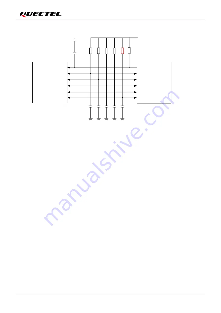
Figure 4: SDIO Interface Connection
To ensure that the interface design complies with the SDIO 3.0 specification, the following principles are
recommended to be adopted:
Route the SDIO traces in inner-layer of the PCB an
d the impedance is controlled at 50 Ω ±10 %;
SDIO signals need to be keep away from sensitive signals, such as radio frequency, analog signals,
clocks, and DC-DC noise signals;
The distance between SDIO signals and other signals must be greater than 2 times the trace width,
and the busload capacitance must be less than 15 pF.
SDIO signal traces need to be treated with equal length (the distance between the traces is less than
1 mm). According to the transmission rate, the trace length has the following requirements:
1) As for SDR104 mode, the recommended bus length is less than 50 mm, the internal trace length
of the module is 11.36 mm.
2) As for other modes, such as DDR50, SDR100, etc., the recommended bus length is less than
150 mm.
3.6. Bluetooth Application Interface
The following figure shows the block diagram of Bluetooth application interface
connection between


