Queclink GV50 User Manual Download Page 17

GV50(P) User Manual 

TRACGV50UM001 

-  16  -

Note: 

1. CELL LED status cannot be configured.
2. GPS LED can be configured to turn off after a period of time using the Manage Tool.
Note:This equipment has been tested and found to comply with the limits for a Class B digital 
device, pursuant to part 15 of the FCC Rules. These limits are designed to provide reasonable 
protection against harmful interference in a residential installation. This equipment generates, 
uses and can radiate radio frequency energy and, if not installed and used in accordance with the 
instructions, may cause harmful interference to radio communications. However, there is no 
guarantee that interference will not occur in a particular installation. If this equipment does 
cause harmful interference to radio or television reception, which can be determined by turning 
the equipment off and on, the user is encouraged to try to correct the interference by one or 
more of the following measures:   


Reorient or relocate the receiving antenna.   

Increase the separation between the equipment and receiver.    

Connect the equipment into an outlet on a circuit different from that to which the receiver is 

connected.    

Consult the dealer or an experienced radio/TV technician for help.   

FCC Statement   
Any Changes or modifications not expressly approved by the party responsible for compliance 

could void the user’s authority to ope

rate the equipment.  

This device complies with part 15 of the FCC Rules. 
Operation is subject to the following two conditions: 
(1) This device may not cause harmful interference, and   
(2) This device must accept any interference received, including interference that may 
cause undesired operation.    
FCC Radiation Exposure Statement: 
This equipment complies with FCC radiation exposure limits set forth for an


uncontrolled environment .This equipment should be installed and operated with minimum 
distance 

20

cm between the radiator& your body.

Summary of Contents for GV50

Page 1: ...GV50 P User Manual GPRS GNSS Tracker TRACGV50UM001 Version 1 01...

Page 2: ...ustomer s possession Furthermore system validation of this product designed by Queclink within a larger electronic system remains the responsibility of the customer or the customer s system integrator...

Page 3: ...ace Definition 8 2 3 1 GV50 External Interface 8 2 3 2 GV50P External Interface 9 2 3 3 Internal Interface 9 2 4 GV50 P Extension Cable Color 10 3 Getting Started 12 3 1 Opening the Case 12 3 2 Closin...

Page 4: ...ABLE 2 GV50 PARTS LIST 8 TABLE3 GV50 P PARTS LIST 8 TABLE 4 DESCRIPTION OF 2 PIN CABLE 9 TABLE 5 DESCRIPTION OF 4 PIN CABLE 9 TABLE 6 GV50 2 PIN EXTENSION CABLE COLOR DEFINITION 10 TABLE 7 GV50P 4 PIN...

Page 5: ...BLE 9 FIGURE 4 GV50P 4 PIN CABLE 9 FIGURE 5 GV50 P MICRO USB CONNECTOR 10 FIGURE 6 OPENING THE CASE 12 FIGURE 7 CLOSING THE CASE 12 FIGURE 8 INSTALLING A SIM CARD 13 FIGURE 9 INSTALLING THE INTERNAL B...

Page 6: ...GV50 P User Manual TRACGV50UM001 5 0 Revision History Revision Date Author Description of Change 1 00 2016 11 28 Pablo Dang Initial 1 01 2017 06 17 Pablo Dang Added GV50P related information...

Page 7: ...nd mobile devices Its built in 3 axis accelerometer allows motion detection and extends battery life through sophisticated power management algorithms System integration is straightforward as complete...

Page 8: ...7 2 Product Overview 2 1 Check Parts List Before starting check all the following items have been included with your GV50 P If anything is missing please contact your supplier Figure 1 Appearance of G...

Page 9: ...le 2 GV50 Parts List Name Picture GV50 Locator User Cable Table3 GV50 P Parts List Name Picture GV50 P Locator User Cable 2 3 Interface Definition 2 3 1 GV50 External Interface GV50 has a 2 PIN cable...

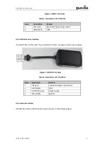
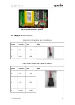
Page 10: ...rnal Interface The GV50P has a 4 PIN cable The pin definition of the 4 pin power cable is shown below Figure 4 GV50P 4 Pin Cable Table 5 Description of 4 Pin Cable Index Description Remark 1 VIN red E...

Page 11: ...nnector 2 4 GV50 P Extension Cable Color Table 6 GV50 2 Pin Extension Cable Color Definition Pin No Definition Color Cable 1 VIN red 2 GND black Table 7 GV50P 4 Pin Extension Cable Color Definition Pi...

Page 12: ...GV50 P User Manual TRACGV50UM001 11 4 IGN white...

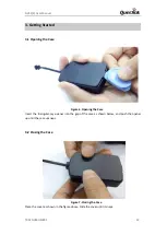
Page 13: ...ase Figure 6 Opening the Case Insert the triangular pry opener into the gap of the case as shown below and push the opener up until the case unsnaps 3 2 Closing the Case Figure 7 Closing the Case Plac...

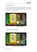
Page 14: ...attery to OFF position Slide the holder right to open the SIM card Insert the SIM card into the holder as shown below with the gold colored contact area facing down Take care to align the cut mark Clo...

Page 15: ...be in the OFF position when shipped on an aircraft 2 When the switch is in the OFF position the battery cannot be charged or discharged 3 To reset the device Remove the external DC power and then swi...

Page 16: ...t are CELL LED and GPS LED LED Device Status LED Status CELL Note 1 Device is searching GSM network Fast flashing Device has been registered to GSM network Slow flashing SIM card needs pin code to unl...

Page 17: ...n the user is encouraged to try to correct the interference by one or more of the following measures Reorient or relocate the receiving antenna Increase the separation between the equipment and receiv...

Reviews: