background image

GV304N User Manual


TRACGV304NUM001

                                                                                                                                  - 17 - 

2.3.


Interface Definition 

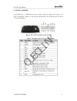
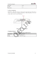
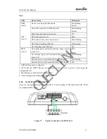
The GV304N has a 16 PIN interface connector which contains the connections for power, I/O, 
RS232, microphone, speaker, etc. The sequence and definition of the 16PIN connector are shown 
in the following figure: 


Figure 2.


The 16 PIN Connector on the GV304N 
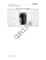
 

Table 4.


Description of 16 PIN Connections 

Index 

Description 

Comment  

MICP 


Single end, 2-2.2k microphone, internal bias   

2 AGND  Analog 

ground 

IGN 

Ignition input, positive trigger 

RXD 

UART RXD, RS232 

5 TXD 

UART 

TXD, 

RS232 

GND 

Power and digital ground 

OUT3 

Open drain, 150 mA max 

OUT2 

Open drain, 150 mA max 

9 EARP 

Differential output, 32 ohm 1/4w speaker 

10 EARN 
11 

PWR 

External DC power input, 8-32V 

12 

IN2 

Digital input, negative trigger 

13 

IN1 

Digital input, negative trigger 

14 

OUT1 

Open drain, 150 mA max ,with latch circuit 

15 AD1/IN3 

Multifunction input, analog or digital input 
0-16V 

16 AD2 

Analog 

input 

0.3-16V 


QUECLINK

Summary of Contents for GV304N

Page 1: ...GV300N User Manual TRACGV300NUM001 7 GSM GPRS GPS Tracker GV304N User Manual Application Notes TRACGV304NUM001 Revision 1 00 Q U E C L I N K...

Page 2: ...system validation of this product designed by Queclink within a larger electronic system remains the responsibility of the customer or the customer s system integrator All specifications supplied here...

Page 3: ...Opening the Case 19 3 2 Closing the Case 19 3 3 Installing a SIM Card 19 3 4 Installing the Internal Backup Battery 20 3 5 Switch ON the Backup Battery 21 3 6 Installing the External GPS Antenna Optio...

Page 4: ...16 PIN CONNECTIONS 17 TABLE 5 GV304N USER CABLE COLOR DEFINITION 18 TABLE 6 GPS ANTENNA SPECIFICATION 21 TABLE 7 ELECTRICAL CHARACTERISTICS OF IGNITION DETECTION 22 TABLE 8 ELECTRICAL CHARACTERISTICS...

Page 5: ...GURE 8 GPS ANTENNA OF GV304N 21 FIGURE 9 TYPICAL POWER CONNECTION 22 FIGURE 10 TYPICAL IGNITION DETECTION 23 FIGURE 11 TYPICAL DIGITAL INPUT CONNECTION 24 FIGURE 12 TYPICAL ANALOG INPUT CONNECTION 24...

Page 6: ...GV304N User Manual 0 Revision History Revision Date Author Description of change 1 00 2016 06 16 Super Zhao Initial Q U E C L I N K...

Page 7: ...S position as well as many other useful functions Users can also use GV304N to monitor the status of a vehicle and control the vehicle by its external relay output System integrators can easily set up...

Page 8: ...r protocol interface between GV304N and backend server 1 2 Terms and Abbreviations Table 2 Terms and Abbreviations Abbreviation Description AGND Analog Ground AIN Analog Input DIN Digital Input DOUT D...

Page 9: ...1 15 2 Product Overview 2 1 Check Parts List Before starting check whether all the following items have been included with your GV304N If anything is missing please contact your supplier Figure 1 Appe...

Page 10: ...04N User Manual TRACGV304NUM001 16 2 2 Parts List Table 3 Parts List Name Picture GV304N Locator 94 57 24 5 mm User Cable Extend Cable Optional GPS Antenna Optional DATA_CABLE_M Optional Q U E C L I N...

Page 11: ...Comment 1 MICP Single end 2 2 2k microphone internal bias 2 AGND Analog ground 3 IGN Ignition input positive trigger 4 RXD UART RXD RS232 5 TXD UART TXD RS232 6 GND Power and digital ground 7 OUT3 Ope...

Page 12: ...Definition Color PIN No Cable PIN No Color Definition OUT2 Yellow 8 16 Brown White AD2 OUT3 Brown 7 15 Green AD1 IN3 GND Black 6 14 Blue OUT1 TXD White Black 5 13 Orange IN1 RXD Pink 4 12 Orange Black...

Page 13: ...he cover on the bottom in the position as shown in the following figure Use a screwdriver clockwise to tighten four screws 3 3 Installing a SIM Card Open the case and ensure the unit is not powered un...

Page 14: ...4NUM001 20 mark Close the SIM card holder Close the case Figure 5 SIM Card Installation 3 4 Installing the Internal Backup Battery Figure 6 Backup Battery Installation There is an internal backup Li i...

Page 15: ...n the switch is on the OFF position the battery cannot be charged or discharged 3 6 Installing the External GPS Antenna Optional There is a SMA GPS antenna connector on GV304N The GV304N will automati...

Page 16: ...this device is from 8V to 32V The device is designed to be installed in vehicles that operate on 12V or 24V systems without the need for external transformers Figure 9 Typical Power Connection 3 8 Ig...

Page 17: ...is running For example the power source for the FM radio IGN signal can be configured to start transmitting information to backend server when ignition is on and enter power saving mode when ignition...

Page 18: ...owing diagram shows the recommended connection Figure 12 Typical Analog Input Connection Note PIN 15 is an multifunction pin it can be configured as a digital input or an analog input 3 11 Digital Out...

Page 19: ...Figure 13 Digital Output Internal Drive Circuit Table 9 Electrical Characteristics of Digital Outputs Logical State Electrical Characteristics Enable 1 5V 150mA Disable Open drain Figure 14 Typical C...

Page 20: ...the output state during reset 2 All outputs are internally pulled up to PWR pin by a diode So no external flyback diode is needed when the output is connected to an inductive load 3 12 Device Status...

Page 21: ...LED Device status LED status GSM note1 Device is searching GSM network Fast flashing Note3 Device has registered to GSM network Slow flashing Note4 SIM card needs pin code to unlock ON GPS note 2 GPS...

Page 22: ...cate with Garmin GPS Set The following typical connection is using Queclink AG100 cable Figure 18 GV304N connection with Garmin GPS set Note GV304N some version maybe connects with Garmin GPS set by G...

Reviews: