background image


RADARAY FOUL DETECTOR MANUAL


400-088-006-01 Rev. A 

Page 6


In an installation where only one detector is used (an odd number of lanes, for example), the foul 

detector for the unused lane can be deactivated through the chassis using the procedure mentioned 

in Section 3.0 

Operation


3. 

OPERATION 

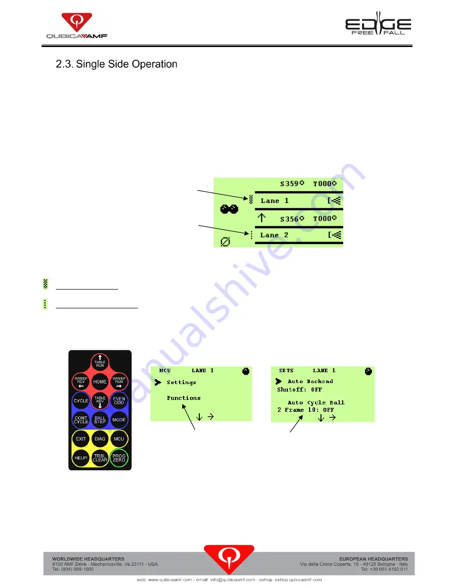
The pinspotter chassis is capable of showing when a lane has the foul detector on or in warning 

mode. On the Main Screen, you will see symbols just to the left of the lane numbers that tell you what 

mode the foul detectors are in (shown in Figure 2). If neither of the icons for the foul detector is 

displayed, then the foul detector is off.  


Figure 2, Foul Detector Icons 


Foul Detector On - Foul turns light on, sounds buzzer, and a foul will count for scoring purposes. 


Foul Detector Warning - Foul turns light on and sounds buzzer, but a foul will not affect the score.  


The foul detector modes can be changed through the pinspotter chassis or handheld unit by using the 

following steps (see Figure 3). 


Figure 3 


1.  Press the 

[MCU]

 button to go into the 

MCU Menus

2.  Press the 

[

]

 button to select the 

Settings Menus

3.  Scroll down by using the 

[

]

 button until the flashing arrow is next to 

Foul Detector

.  

4.  Pressing the 

[

]

 button will cycle through the possible choices for the foul detector.  


MCU Menus 

Settings Menus 

Foul Detector On 

Foul Detector Warning Mode 


Summary of Contents for EDGE RADARAY

Page 1: ...EDGE RADARAY Pinspotter Manual Supplement Appendix H These Original Instructions were written in English 400 088 006 01 Rev A June 2022...

Page 2: ......

Page 3: ...e held responsible for any claims resulting from these errors DOCUMENT UPDATES This manual supersedes all previous versions of the EDGE Radaray Owner s Manual QubicaAMF Worldwide LLC reserves the righ...

Page 4: ......

Page 5: ...Radaray Foul Detector Manual 400 088 006 01 Rev A Summary of Changes Change No ECR No Rev A 22 0001 List of Effective Pages Page Change No Effective Date All Rev A 6 10 2022...

Page 6: ......

Page 7: ...RADARAY FOUL DETECTOR MANUAL 400 088 006 01 Rev A Page 1 Appendix H Radaray Foul Detector Manual...

Page 8: ......

Page 9: ...Page 3 Contents Appendix H Radaray Foul Detector Manual 1 1 GENERAL INFORMATION 3 2 INSTALLATION AND ALIGNMENT PROCEDURE 3 2 1 Installation 3 2 2 Alignment Procedure 4 2 3 Single Side Operation 6 3 O...

Page 10: ......

Page 11: ...ounted in the control unit cover and causes a beeper to sound for approximately 13 seconds 2 INSTALLATION AND ALIGNMENT PROCEDURE Reflector Assembly The reflector unit mounts at the end of the common...

Page 12: ...ping 10 x 1 hex head screws provided 4 Before installing the cover complete the alignment procedure in accordance with section 2 2 5 Once aligned insert a lens in each opening in the sides of the cove...

Page 13: ...embly until the LED light goes out and tighten the screws The horizontal beam alignment is now complete Note It is very unlikely that the vertical beam alignment will be incorrect Apply some slight pr...

Page 14: ...for the foul detector is displayed then the foul detector is off Figure 2 Foul Detector Icons Foul Detector On Foul turns light on sounds buzzer and a foul will count for scoring purposes Foul Detect...

Page 15: ...leaning recommendations 1 Use a clean non abrasive cloth to gently wipe the face of the reflectors on the reflector unit and the optics window on the EDGE Radaray base cover 2 If gently wiping does no...

Page 16: ...RADARAY FOUL DETECTOR MANUAL 400 088 006 01 Rev A Page 8...

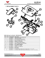
Page 17: ...88 000 079 LENS FOUL DETECTOR 6 4 088 000 087 PHPMS 1 4 20 X 0 50 BO 7 1 088 000 283 FOUL DETECT WIRE HARNESS 8 1 088 000 221 QAMF XLI RADAR CVR LED BOARD 9 2 088 000 421 FOUL SENSOR BRACKET 10 1 090...

Page 18: ......

Reviews: