


HyperTrack™
Software Instruction
90
Quasonix, Inc.
!WARNING!
Always ensure there are no persons servicing the positioner prior to applying power to the
system. A visual check or headphone communications to someone close to the positioner is
essential. OBEY ALL WARNING LIGHTS and BUZZERS.
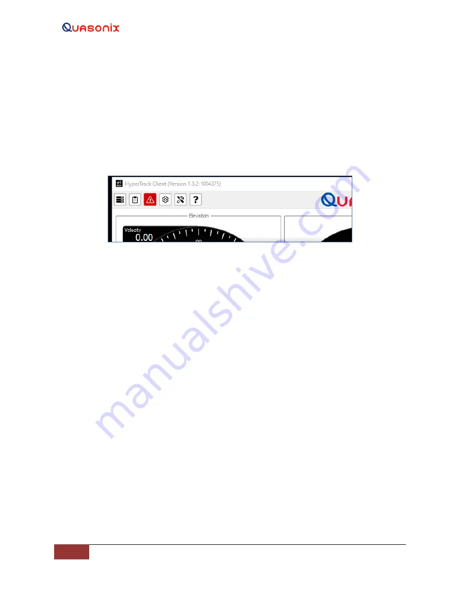
When an interlock or fault is present, the Status icon, located on the Tool Bar at the top of the screen, flashes red
indicating that an interlock or fault condition has occurred, as shown in Figure 106. The Servo button is disabled and
displays gray until the interlock or fault is cleared. The servo power to the positioner is not available until the critical
fault or interlock is removed and the Status Indicator is clear.
Figure 106: Main Screen, Tool Bar
—
Red Status Icon
The system interlocks include:
•
Run/Safe Switch
•
Stow Pin
•
Local Control (Hand-Held)
•
Shorting Plug (located at the servo amplifier assembly box)
•
Man on Platform Interlock (2 - minute wait state)
•
External Interlock (Optional and specific to the system)
The external interlock is used for customer specific requirements or specific types of installs, such as trailer
systems. On a trailer, an interlock connect would be added to the tool box lid, so the system
won’t
hit the
tool box.
When no interlocks are present, the servos may be energized by selecting the red Servo button. The servos are
powered On only after a fixed transition time with audible alarm. The alarm at the positioner alerts any personnel
working on, or close to, the positioner that the system is operation and capable of movement. During the transition
time, the Servo button illuminates yellow until the axes are enabled and warning alarm completes. The transition
alarm time is not configurable in HyperTrack™ systems. It is a fixed, 30 second timeout.
After the transition time, the power is applied to the servos and the Servo button changes to green. The user now has
access to the Azimuth and Elevation axis mode control buttons.
The servos in any other state will not allow access to the Mode Control buttons. The Mode Control buttons are
disabled (gray).
4.2.3.4.2 Modes of Operation
There are six (6) standard modes of Azimuth and Elevation axes control. The Manual mode allows user input from
the graphical user interface (GUI), handwheels, a joystick, or keyboard arrow keys. Those modes include:


