


HyperTrack™
Software Instruction
89
Quasonix, Inc.
4.2.3.4
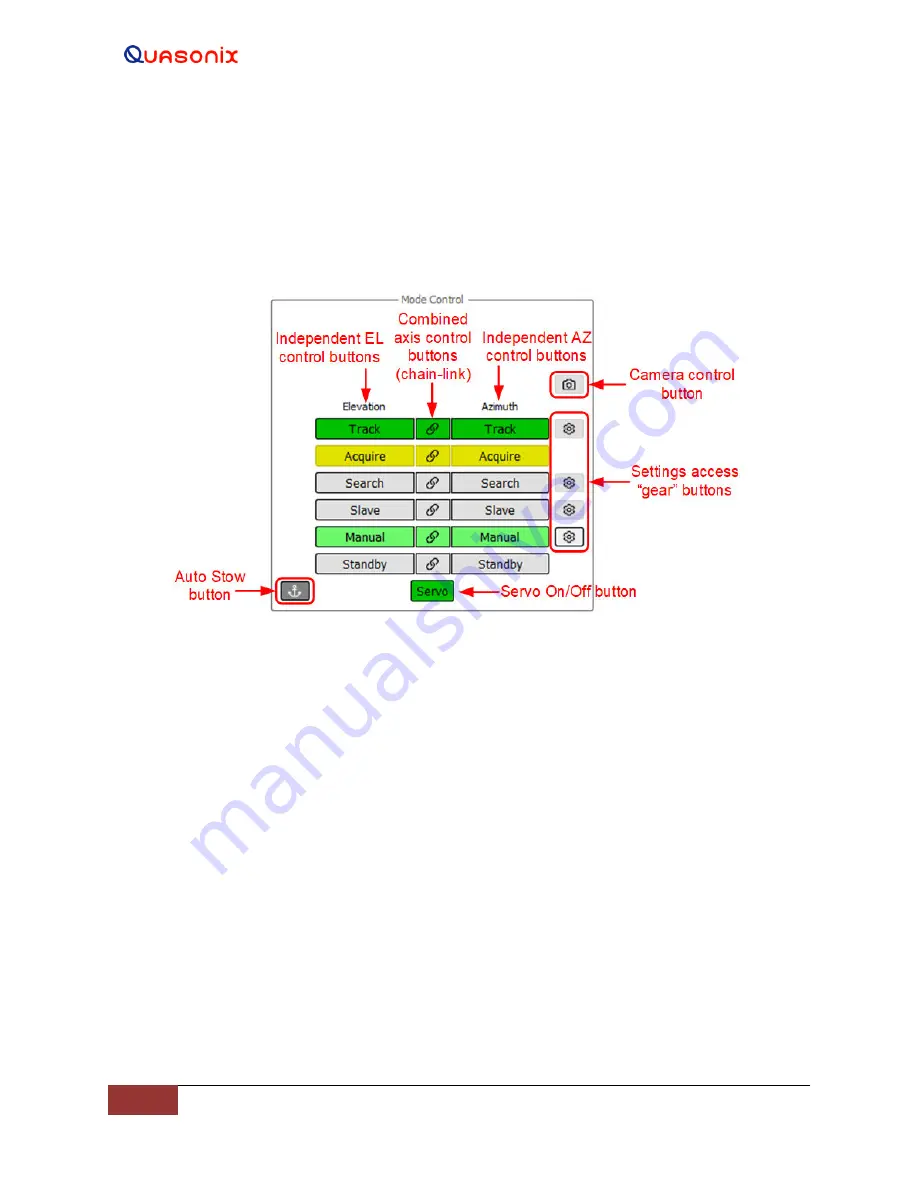
Mode Control
The Mode Control window on the main GUI screen, shown in Figure 105, is used to manually configure and control
the Azimuth and Elevation axes. It shows the independent AZ and EL axis control modes, Combined axis control
buttons, Camera control button, Servo On/Off button, and the settings access (Gear button) for corresponding mode.
When the Gear button is selected, an additional settings configuration window displays to the right of Mode Control
window. An Auto Stow button may display if this option is installed and enabled.
Figure 105: Main Screen, Mode Control Window
The Mode Control window includes the following functions: Track, Acquire, Search, Slave, Manual, Standby, and
Servo.
4.2.3.4.1 Servo
The Servo power button is located at the bottom center of the Mode Control window. Selecting the Servo button
provides (AC) power to the Azimuth and Elevation Axes servo amplifiers, located within the servo power assembly.
When the Servo button displays red, the servos are Off/Disabled.
When the Servo button is selected, it changes color to yellow and a timed audible warning indicator sounds. This is
the transition alarm period. When the alarm ends, the Servo button changes to green. This indicates that both the
Azimuth and Elevation servos are powered (On/Enabled) and ready to be commanded.
However, both axes are not enabled until the Manual buttons are selected and display in green. If a system interlock
is present, the servo cannot be powered on and the Servo button will stay disabled (gray) until the interlock is
cleared.
When the Servo button is gray, it indicates a fault or safe condition has rendered the Servo button unavailable to the
user.


