3
rd
Generation Dual Channel
Compact RDMS
TM
Telemetry Receiver-Combiner
47
Quasonix, Inc.
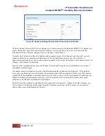
Figure 53: System Block Diagram with Best Channel Selector
This process yields optimal data output on a single connector under all conditions. The only penalty for this
performance improvement is increased processing latency in the RDMS™, approximately equal to one DQE frame.
Refer to section 5.4.2.5 for details about DQE.
When the BCS is disabled, the back-panel data output from the Combiner comes from the Diversity Combiner
demodulator, as it traditionally has.
Another unique advantage of the BCS is that its output can be encapsulated using IRIG-standard Data Quality
Encapsulation (DQE) for use by an external Best-Source Selector (BSS). This capability allows spatial diversity
across a vast range with a minimal number of BSS channels and attendant bandwidth. Further, since the BCS need
only accommodate relatively miniscule latency differences between its inputs, its local performance may exceed that
of a BSS designed to handle several seconds of time delay between channels. Driving an external BSS with several
RDMS™ BCS outputs leverages the strengths of both.
5.4.3.7
Time Aligner
The Time Aligner option is only available with the Combiner option enabled and set to On. The Time Aligner can
be disabled or enabled. When disabled, it remains Off and does not affect the combiner.
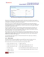
Clicking on the check box to enable the (combiner) time aligner, as shown in Figure 54, lets it determine when to
operate (with no user intervention).


