3
rd
Generation Dual Channel
Compact RDMS
TM
Telemetry Receiver-Combiner
48
Quasonix, Inc.
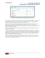
Figure 54: Advanced Settings Window, Time Aligner Selection Checked
Maximal ratio combining can only achieve optimal performance if the Channel 1 and Channel 2 input signals are
accurately phase- and time-aligned. Traditionally, diversity combiners have performed phase alignment only, relying
on the telemetry system design to provide adequate time alignment.
However, there are cases in which time alignment cannot be easily guaranteed. Such cases include frequency
diversity and spatial diversity, where the propagation of transmit and receive paths for Channel 1 and Channel 2 may
be quite different through cables, equipment, and the air. As bit rates continue to increase, fixed latency differences
are magnified in relation to the bit period.
The Quasonix RDMS™ Combiner can perform both phase alignment and time alignment of the Channel 1 and
Channel 2 signals. The Time Aligner is capable of correcting up to ±1300 nanoseconds of time skew between
channels (about a quarter mile of free-space propagation). Similar to phase alignment, time alignment is dynamic,
accommodating changes in relative target antenna positions over time.
When enabled, the Time Aligner continuously measures skew between channels but remains in a “monitor” state
(with no timing correction) as long as the skew remains below a predefined threshold. When the skew exceeds the
threshold, the Time Aligner switches to a “run” state (with full timing correction) as long as the signal quality is
sufficient for it to continue to track timing skew.
If the propagation delay between channels is well-controlled and small, the Time Aligner may be disabled to
guarantee minimal timing jitter.
5.4.4
PCM Encoding
The PCM Encoding setting controls the RDMS receiver output PCM data format. Two primary options are
available: the receiver can convert encoded data to NRZ-L, or it can preserve transmit encoding.
The first option allows conversion of any of the following encoding formats to NRZ-L:
•
NRZ-L: Non-return-to-zero, level
•
NRZ-M: Non-return-to-zero, mark
•
NRZ-S: Non-return-to-zero, space
•
RZ: Return-to-zero
•
Biphase-L: Biϕ, level
•
Biphase-M: Biϕ, mark
•
Biphase-S: Biϕ, space
•
DM-M: Delay modulation (Miller code), mark
•
DM-S: Delay modulation (Miller code), space
•
M2-M: Modified delay modulation (Miller squared code), mark
•
M2-S: Delay modified modulation (Miller squared code), space


