background image

- 2 -

 Service Manual


Important Safety Notice

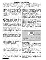
Special components are used in this projection television which are important for safety. These components are

identified on the schematic diagram by the symbol 

 and printed in BOLD TYPE on the replacement part list. It is

essential that these critical parts are replaced with the manufacturer’s specified replacement part to prevent x-ray
radiation, shock, fire or other hazards. Do not modify the original design without the manufacturer’s permission.

Safety Precautions

General Guidelines

An 

isolation transformer

 should always be used

during the servicing of a PTV whose chassis is not
isolated from AC power line. Use a transformer of
adequate power rating as this protects the technician
from accidents resulting in personal injury from
electrical shocks. It will also protect the PTV from being
damaged by accidental shorting that may occur
during servicing.
When servicing, observe the original lead dress,
especially in the high voltage circuit. Replace all
damaged parts (also parts that show signs of
overheating.)
Always replace protective devices, such as
fishpaper, isolation resistors and capacitors, and
shields after servicing the PTV. Use only
manufacturer’s recommended rating for fuses, circuits
breakers, etc.
High potentials, as high as 32kV, are present when this
PTV is operating. Operation of the PTV without the rear
cover introduces danger for electrical shock. Servicing
should not be performed by anyone who is not
thoroughly familiar with the necessary precautions
when servicing high-voltage equipment.
Extreme care should be practiced when handling the

picture tube

. Rough handling may cause it to implode

due to atmospheric pressure. (14.7 lbs. per sq. in.). Do
not nick or scratch the glass or subject it to any undue
pressure. When handling, use safety goggles and
heavy gloves for protection. Discharge the picture
tube
 by shorting the anode to chassis ground (not to
the cabinet or to other mounting hardware). When
discharging connect cold ground (i.e. DAG ground
lead) to the anode with a well insulated wire or use a
grounding probe.

X-ray Precautions

The front area (between the projection tube and the
lens) is enclosed by a metal box to ensure positive
safety during normal and abnormal conditions when
checking and repairing. To fully ensure safety, the
following precautions must be observed.
1.

Do not remove the lens or metal box.

2.

Make sure to turn the power OFF when the lens is
removed or when checking the cleanliness of the
lens.

3.

Do not remove the lens or metal box to check the
projection tube for operation by watching it directly.
Use a mirror or paper to view the image.

Before returning a serviced PTV to the owner, the
service technician must thoroughly test the unit to
ensure that is completely safe to operate. Do not use a
line isolation transformer when testing.

Leakage Current Cold Check

Unplug the AC cord and connect a jumper between the
two plug prongs. Press the POWER switch ON.
Measure the resistance between the jumpered AC plug
and expose metallic parts such as screw heads,

antenna terminals, control shafts, etc. If the exposed
metallic part has a return path to the chassis, the
reading should be between 240k

Ω 

and 5.2M

Ω. 

If the

exposed metallic part does not have a return path to
the chassis, the reading should be infinite.

Leakage Current Hot Check 

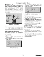
(See Figure 1)

Plug the AC cord directly into the AC outlet. Do not use
an isolation transformer during the check.
Connect a 1.5k

 10 watt resistor in parallel with a

0.15

µ

F capacitor between and exposed metallic part

and ground. Use earth ground, for example a
water pipe.
Using a DVM with a 1000 ohms/volt sensitivity or
higher, measure the AC potential across the resistor.
Repeat the procedure and measure the voltage
present with all other expose metallic parts.
Verify any potential does not exceed 0.75 volt RMS. A
leakage current tester (such a Simpson Model 229,
Sencore Model PR57 or equivalent) may be used in
the above procedure, in which case any current
measure must not exceed 1/2 milliamp. If any
measurement is out of the specified limits, there is a
possibility of a shock hazard and the PTV must be
repaired and rechecked before it is returned to
the customer.

Insulation Test

Connect an insulation tester between an exposed
metallic part and AC line.
Apply 1080VAC/60Hz for 1 second. Confirm that the
current measurement is 0.5mA ~ 2.0mA. Repeat test
with other metallic exposed parts.

X-ray Radiation

WARNING: The potential source of X-ray radiation in the
PTV is in the high voltage section and the picture tube.

Note:  It is important to use an accurate, calibrated

high voltage meter.

Set  brightness, picture, sharpness and color
controls to Minimum.
Measure the High Voltage. The high should be 31.5kV
± 1.0kV
. If the upper limit is out of tolerance, immediate
service and correction is required to insure safe
operation and to prevent the possibility of premature
component failure.

0.15

µ

F

Figure 1.  Hot Check Circuit

COLD 
WATER 
PIPE 
(GROUND)

TO INSTRUMENT’S 
EXPOSED METAL 
PARTS

1500

,10W

AC VOLTMETER

Summary of Contents for SR5133B - 51" PROJECTION TV

Page 1: ...gers in attempting to service a product Products powered by electricity should be serviced or repaired only by experienced professional technicians Any attempt to service or repair the product or prod...

Page 2: ...wer OFF when the lens is removed or when checking the cleanliness of the lens 3 Do not remove the lens or metal box to check the projection tube for operation by watching it directly Use a mirror or p...

Page 3: ...cted to D Board 5 Connect the 8 15 V DC variable power supply to TPB10 and TPBGND on B Board Procedures 1 Apply a monoscope pattern 2 Adjust the Picture or Brightness controls so that the DVM reads 17...

Page 4: ...4 Service Manual Important Safety Notice 2 Safety Precautions 2 Important Safety Tests 3 Service Notes 5 PCB Designation 7 Receiver Feature Table 8 Remote Location of Controls EUR511516 9 Parts List 1...

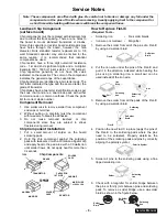
Page 5: ...ldering pads with tweezers or with a miniature alligator clip and apply heat to the pad area with a 30 watts iron until solder flows Do not apply heat for more than 3 seconds How to Replace Flat IC Re...

Page 6: ...or incorrect voltages will be measured WARNING This PTV has been designed to meet or exceed applicable safety and X ray radiation protection as specified by government agencies and independent testing...

Page 7: ...T drive LG Board TNPA0783BA Green CRT drive LR Board TNPA0782BA Red CRT drive N Board TNP2AA027AB 2nd tuner R Board TNPA0615 Remote sensor T Board TNP2AA045AD Line filter X Board TNP2AA063AB A V input...

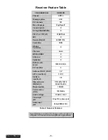
Page 8: ...SAP DBX X AI Sound X Spatializer X Built in audio power 10W CH 10 of speakers 2 Audio out FAO F VAO V F V A V in rear front 3 2 1 S VHS in rear front 1 0 Dimension mm WxDxH in 1137x651x1361 5 44 8x25...

Page 9: ...OL volume Buttons Press to adjust TV sound level Use with Channel buttons to navigate in menus R TUNE Rapid Tune Button Press to switch to the previous channel ACTION Button Press to display Main Menu...

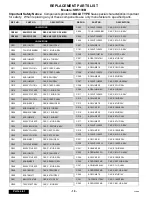
Page 10: ...J2VF1H103Z CAP C 01UF Z 50V C047 ECA0JM222 CAP E 2200UF 6 3V C048 ECJ2VF1H103Z CAP C 01UF Z 50V C049 ECA1EM101 CAP E 100UF 25V C050 ECA1EM471 CAP E 470UF 25V C051 EEUFC1E470B CAP E 47UF 25V C052 TACCX...

Page 11: ...C459 ECA1VM471 CAP E 470UF 35V C460 ECQM1103KZ CAP P 01UF K 100V C461 ECCD2H180JC CAP C 18UF 500V C463 ECQB1H103JM CAP P 01UF J 50V C464 TACCX103T50V CAP C 01UF 50V REF NO PART NO DESCRIPTION C465 ECQ...

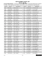
Page 12: ...C819 ECQB1H102JM CAP P 1000PF J 50V C820 ECA1VM470 CAP E 47UF 35V C821 ECQB1H102JM CAP P 1000PF J 50V C822 TACCW391T50V CAP C 390PF 50V C823 ECQB1H471JF CAP P 0047UF J 50V C824 ECEA1VGE101 CAP E 100UF...

Page 13: ...1607 ECA1CM101 CAP E 100UF 16V C1608 ECJ2VC1H101J CAP C 100PF J 50V C1609 ECJ2VC1H101J CAP C 100PF J 50V C1801 ECJ2VF1H103Z CAP C 01UF Z 50V C1802 ECQV1H154JM CAP P 15UF J 50V REF NO PART NO DESCRIPTI...

Page 14: ...F Z 50V C2312 ECJ2VF1H473Z CAP C 047UF Z 50V C2313 ECJ2VF1H104Z CAP C 1UF Z 50V C2314 ECJ2VF1H104Z CAP C 1UF Z 50V C2315 ECJ2VF1H104Z CAP C 1UF Z 50V C2316 ECA1HM221 CAP E 220UF 50V C2317 ECJ2VF1H104Z...

Page 15: ...PF J 50V C3041 ECA1HM100 CAP E 10UF 50V C3054 ECA1CM471 CAP E 470UF 16V C3071 ECJ2VF1H103Z CAP C 01UF Z 50V C3072 ECA1HM100 CAP E 10UF 50V C3073 ECA1HM100 CAP E 10UF 50V REF NO PART NO DESCRIPTION C30...

Page 16: ...V C7038 ECJ2VF1C105Z CAP C 1 0UF Z 16V C7039 ECJ2VF1C105Z CAP C 1 0UF Z 16V C7051 ECA1HM100 CAP E 10UF 50V C7052 ECA1VM470 CAP E 47UF 35V C7053 ECEA1CN101U CAP E 100UF 16V DIODES D004 MA4330H DIODE D0...

Page 17: ...ODE ZENER D760 MA152K DIODE D802 RBV 408 BRIDGE RECTIFIER D804 MA165 DIODE D816 MA700 DIODE D817 AU01Z DIODE D818 MA4220L DIODE ZENER D819 TMPG10G3 DIODE D821 MA165 DIODE D822 ERA22 02 DIODE D831 RU30...

Page 18: ...IODE D4154 MA152K DIODE D4301 MA3036H DIODE D7031 MA3091M DIODE D7051 MA152K DIODE D7052 MA152K DIODE FUSES F2801 0BA1C63NU100 FUSE 6 3A 125V REF NO PART NO DESCRIPTION INTEGRATED CIRCUITS IC001 MN102...

Page 19: ...LSA35T FERRITE BEAD L806 EXCELSA35T FERRITE BEAD L808 EXCELDR35 FERRITE BEAD L810 EXCELSA35T FERRITE BEAD L811 EXCELSA35T FERRITE BEAD L812 EXCELSA35B FERRITE BEAD L831 EXCELSA35B FERRITE BEAD L832 EX...

Page 20: ...011 TRANSISTOR Q356 2SB1011 TRANSISTOR Q373 2SC3063 TRANSISTOR Q374 2SC3063 TRANSISTOR Q375 2SB1011 TRANSISTOR Q376 2SB1011 TRANSISTOR Q393 2SC3063 TRANSISTOR Q394 2SC3063 TRANSISTOR Q395 2SB1011 TRAN...

Page 21: ...01ARTX TRANSISTOR Q2101 2SD601ARTX TRANSISTOR Q2351 2SB709ARTX TRANSISTOR Q2352 2SD601ARTX TRANSISTOR Q2353 2SB709ARTX TRANSISTOR Q2354 2SD601ARTX TRANSISTOR Q2355 2SB709ARTX TRANSISTOR Q2401 2SD601AR...

Page 22: ...GEYJ102 RES M 1K J 1 10 R050 ERJ6GEYJ103 RES M 10K J 1 10 R051 ERJ6GEYJ471 RES M 470 J 1 10 R052 ERJ6GEYJ101 RES M 100 J 1 10 R053 ERJ6GEYJ101 RES M 100 J 1 10 R054 ERJ6GEYJ152 RES M 1 5K J 1 10 REF N...

Page 23: ...RES M 2 2K J 1 10 R319 ERDS2TJ102 RES C 1K J 1 4 R320 ERDS2TJ102 RES C 1K J 1 4 R321 ERDS1TJ104 RES C 100K J 1 2 R325 ERJ6ENF5601 RES M 5 6K F 1 10 R327 ERJ6ENF2201 RES M 2 2K F 1 10 R328 ERDS2TJ102 R...

Page 24: ...22 RES C 1 2K J 1 2 R462 ERDS2TJ333 RES C 33K J 1 4 R463 ERDS2TJ224 RES C 220K J 1 4 R465 ERDS2TJ471 RES C 470 J 1 4 R466 ERDS2TJ153 RES C 15K J 1 4 R467 ERDS2TJ564 RES C 560K J 1 4 REF NO PART NO DES...

Page 25: ...RES M 1 5K J 1 10 R624 ERJ6GEYJ272 RES M 2 7K J 1 10 R625 ERJ6GEYJ102 RES M 1K J 1 10 R627 ERJ6GEYJ222 RES M 2 2K J 1 10 R628 ERJ6GEYJ471 RES M 470 J 1 10 R631 ERJ6GEYJ102 RES M 1K J 1 10 R632 ERJ6GEY...

Page 26: ...ES M 18 J 2W R941 ERJ6GEYJ101 RES M 100 J 1 10 R942 ERJ6GEYJ123 RES M 12K J 1 10 R943 ERJ6GEYJ222 RES M 2 2K J 1 10 R944 ERJ6GEYJ331 RES M 330 J 1 10 R945 ERJ6GEYJ152 RES M 1 5K J 1 10 REF NO PART NO...

Page 27: ...M 330 J 1 10 R1603 ERJ6GEYJ331 RES M 330 J 1 10 R1604 ERJ6GEYJ182 RES M 1 8K J 1 10 R1605 ERJ6GEYJ102 RES M 1K J 1 10 R1606 ERJ6GEYJ333 RES M 33K J 1 10 R1607 ERJ6GEYJ681 RES M 680 J 1 10 REF NO PART...

Page 28: ...R2115 EVND8AA03B33 CONTROL 3K R2117 ERJ6GEYJ121 RES M 120 J 1 10 R2118 EVND8AA03B14 CONTROL 10K R2119 ERJ6GEYJ392 RES M 3 9K J 1 10 R2121 ERJ6GEYJ471 RES M 470 J 1 10 R2122 ERJ6GEYJ473 RES M 47K J 1 1...

Page 29: ...GEYJ221 RES M 220 J 1 10 R3022 ERJ6GEYJ221 RES M 220 J 1 10 R3024 ERJ6GEYJ221 RES M 220 J 1 10 R3026 ERJ6GEYJ102 RES M 1K J 1 10 R3027 ERJ6GEYJ221 RES M 220 J 1 10 R3028 ERJ6GEYJ102 RES M 1K J 1 10 RE...

Page 30: ...6GEYJ472 RES M 4 7K J 1 10 R4140 ERJ6GEYJ472 RES M 4 7K J 1 10 R4141 ERJ6GEYJ471 RES M 470 J 1 10 R4142 ERJ6GEYJ152 RES M 1 5K J 1 10 R4143 ERJ6GEYJ221 RES M 220 J 1 10 R4144 ERJ6ENF3900 RES M 390 F 1...

Page 31: ...3 RES M 3 3 J 1W R7031 ERJ6GEYJ222 RES M 2 2K J 1 10 R7032 ERJ6GEYJ222 RES M 2 2K J 1 10 R7033 ERJ6GEYJ222 RES M 2 2K J 1 10 R7035 ERX1SJ5R6 RES M 5 6 J 1W R7040 ERX1SJ3R3 RES M 3 3 J 1W R7045 ERX1SJ5...

Page 32: ...BLOCK M019 TQB2AA7081 REMOTE GUIDE M020 TQB2AA0367 MANUAL OWNERS M021 TQB2AA7076 V CHIP ROLLER GUIDE M022 TSX2AA0131 LINE CORD SPT2 M023 TXFBX11BSER ASSY 7 KEY BUTTON REF NO PART NO DESCRIPTION M024...

Reviews: