background image

4

For assistance, please call : 1-800-211-PANA(7262) or send e-mail to : [email protected]

1.

Read Instructions – All the safety and
operating instructions should be read before
the unit is operated.

2.

Retain Instructions – The safety and
operating instructions should be retained for
future reference.

3.

Heed Warnings – All warnings on the unit
and in the operating instructions should be
adhered to.

4.

Follow Instructions – All operating and
maintenance instructions should be followed.

5.

Cleaning – Unplug this video unit from the
wall outlet before cleaning. Do not use liquid
or aerosol cleaners. Use a dry cloth for
cleaning.

6.

Attachments – Do not use attachments not
recommended by the video product
manufacturer as they may be hazardous.

7.

Water and Moisture – Do not use this video
unit near water – for example near a bath tub,
wash bowl, kitchen sink, or laundry tub, in a
wet basement, or near a swimming pool, and
the like.

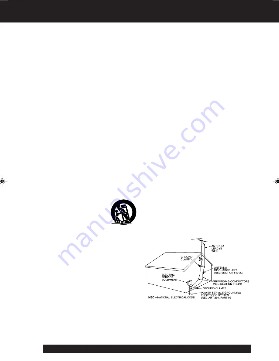
8.

Accessories – Do not place this video unit
on an unstable cart, stand, tripod, bracket, or
table. The video unit may fall, causing serious
injury to a child or adult, and serious damage
to the unit. Use only with a cart, stand, tripod,
bracket, or table recommended by the
manufacturer, or sold with the video unit. Any
mounting of the unit should follow the
manufacturer’s instructions and should use a
mounting accessory recommended by the
manufacturer. An appliance and cart
combination should be moved
with care. Quick stops,
excessive force, and uneven
surfaces may cause the
appliance and cart combination
to overturn.

9.

Ventilation – Slots and openings in the
cabinet are provided for ventilation and to
ensure reliable operation of the video unit
and to protect it from overheating. These
openings must not be blocked or covered.
Never place the video unit on a bed, sofa,
rug, or other similar surface, or near or over a
radiator or heat register. This video unit
should not be placed in a built-in installation
such as a bookcase or rack unless proper
ventilation is provided or the manufacturer’s
instructions have been adhered to.

10. Power Sources – This video unit should be

operated only from the type of power source
indicated on the marking label. If you are not
sure of the type of power supply to your
home, consult your appliance dealer or local
power company. For video units intended to
be operated from battery power, or other
sources, refer to the operating instructions.

Important Safeguards

11. Grounding or Polarization – This video unit

may be equipped with either a polarized
2-wire AC (Alternating Current) line plug (a
plug having one blade wider than the other)
or 3-wire grounding type plug, a plug having a
third (grounding) pin.
The 2-wire polarized plug will fit into the
power outlet only one way. This is a safety
feature. If you are unable to insert the plug
fully into the outlet, try reversing the plug. If
the plug still fails to fit, contact your electrician
to replace your obsolete outlet.
Do not defeat the safety purpose of the
polarized plug.
The 3-wire grounding type plug will fit into a
grounding type power outlet. This is a safety
feature. If you are unable to insert the plug
into the outlet, contact your electrician to
replace your obsolete outlet. Do not defeat
the safety purpose of the grounding type plug.

12. Power-Cord Protection – Power-supply

cords should be routed so that they are not
likely to be walked on or pinched by items
placed upon or against them. Paying
particular attention to cords of plugs,
convenience receptacles, and the point where
they exit from the unit.

13. Outdoor Antenna Grounding – If an outside

antenna or cable system is connected to the
video unit, be sure the antenna or cable
system is grounded so as to provide some
protection against voltage surges and built-up
static charges. Part 1 of the Canadian
Electrical Code, in USA Section 810 of the
National Electrical Code, provides information
with respect to proper grounding of the mast
and supporting structure, grounding of the
lead-in wire to an antenna discharge unit, size
of grounding conductors, location of antenna
discharge unit, connection to grounding
electrodes, and requirements for the
grounding electrode.

14. Lightning – For added protection of this

video unit receiver during a lightning storm, or
when it is left unattended and unused for long
periods of time, unplug it from the wall outlet
and disconnect the antenna or cable system.
This will prevent damage to the video unit due
to lightning and power-line surges.

01.L152 Getting p01-07

02.2.18, 1:38 PM

4

Summary of Contents for Palmcorder VM-L152

Page 1: ...structions Model No LSQT0598A VM L152 For assistance please call 1 800 211 PANA 7262 or send e mail to consumerproducts panasonic com Please read these instructions carefully before attempting to oper...

Page 2: ...rmation source Date of Purchase Dealer Purchased From Dealer Address Dealer Phone No Model No Serial No These accessories are provided in order to set up or use your Camcorder Unpack your Camcorder 1...

Page 3: ...s bottom cover This device complies with Part 15 of the FCC Rules Operation is subject to the following two conditions 1 This device may not cause harmful interference and 2 this device must accept an...

Page 4: ...er source indicated on the marking label If you are not sure of the type of power supply to your home consult your appliance dealer or local power company For video units intended to be operated from...

Page 5: ...na system should not be located in the vicinity of overhead power lines or other electric light or power circuits or where it can fall into such power lines or circuits When installing an outside ante...

Page 6: ...ng Power Battery Charge Use Refresh Care AC Adaptor Car Battery Cord 8 9 Cassette Information 10 Before Using Remove the Sensor tag Using the Shoulder and Hand Straps Lens Cap 11 Using MENU Mode 12 Se...

Page 7: ...ge 10 4Press here to close door 1 Press LCD OPEN to unlock the LCD monitor Swing it fully open and adjust the angle see above Charging the Battery Pack Charge Battery Pack fully before operation page...

Page 8: ...t even after a sufficient charge discard Battery properly pages 9 31 Charge Battery Pack fully before use 1Plug in AC Adaptor POWER Lamp lights 2Insert Battery A Align left side of Battery with left e...

Page 9: ...h supplied DC Power Cable 2 Plug in AC Adaptor POWER Lamp lights DC IN Connector DC Power Cable POWER Lamp DC OUT Connector DC IN Connector This unit will operate on 110 120 220 240 V AC 50 60 Hz An A...

Page 10: ...JECT switch 5 1 To prevent accidental erasing break off tab with screwdriver Or slide tab open 2 To record again cover hole with adhesive tape Or slide tab closed Protects tapes from being accidentall...

Page 11: ...ugh Strap Rings on Camcorder 3 Re insert the strap ends into buckles Hand Strap 1 2 3 min 25 4 mm 1 inch Attaching the Lens Cap Strap Thread the Strap through the Lens Cap attachment ring as illustrat...

Page 12: ...canceled if UP DOWN DISPLAY or MENU are not pressed within 30 seconds when Self Demo mode is on 1 2 3 4 5 6 7 8 MENU Mode VCR Screen MENU Mode CAMERA Screen 1 PROGRAMMED REC page 18 Camcorder starts...

Page 13: ...Time 1 Press MENU for MENU mode Press UP or DOWN to select CLOCK SET 2 Press DISPLAY for CLOCK SET menu Press UP or DOWN to select TIME ZONE DST or DATE TIME 3 Press DISPLAY for menu of item selected...

Page 14: ...Press DISPLAY to confirm entry DST AUTO Press or hold down UP or DOWN to select hour then press DISPLAY to fix Repeat for minute month day and year Clock starts when year is entered and DISPLAY is pr...

Page 15: ...xit 3 Press LIGHT repeatedly for Light ON OFF or AUTO In AUTO light turns itself on off according to lighting conditions Replacing the Bulb Before you begin Order Part No VLLW0015 for replacement bulb...

Page 16: ...ect to view the recording 3 LCD Press BRIGHT ADJUSTMENT to adjust LCD monitor brightness level EVF Look into EVF and adjust VISION ADJUSTMENT to your eyesight 4 Hold down TAPE SPEED for about 1 second...

Page 17: ...rding by pressing RECORD PAUSE two times Stand by Quick Release is set to OFF at the factory a Press RECORD PAUSE to stop recording bSet POWER to OFF and leave cassette in Camcorder c To resume record...

Page 18: ...rt time by 30 minutes 3 Press DOWN to select REC TIME Press DISPLAY repeatedly to select one of the options shown at left To cancel the setup press MENU twice 4 Press RECORD PAUSE to place Camcorder i...

Page 19: ...if played or fast forwarded to end Note Using LCD monitor reduces battery operation time Return LCD monitor to locked position when not in use 1 Press LCD OPEN and swing LCD monitor fully open If you...

Page 20: ...r Viewing Remove Battery lid and insert AA battery Do not reverse polarity Replace battery when tape loading unloading takes longer than usual 1 Turn cassette Tape Wheel in direction of arrow to take...

Page 21: ...C then STILL PAUSE on VCR 4Press STILL on Camcorder and STILL PAUSE on VCR to start copying 5Press STOP on both units to stop copying Note Camcorder will only playback tapes recorded in SP or SLP mode...

Page 22: ...power source Set POWER to CAMERA Zoom in close up and out wide angle in one of four speeds ranging from slow 16 seconds to fast 2 seconds Use when subject is darker than surroundings in shadowed area...

Page 23: ...zoom in 3 Press UP FAR or DOWN NEAR until subject is in focus Back away from subject if necessary 4 Hold down W wide angle on POWER ZOOM as desired Refocus as needed when aiming at new scenes Before...

Page 24: ...s stroke when viewed on Camcorder or 3 or 4 head VCR High Speed Shutter Before you begin Connect Camcorder to power source Insert cassette with record tab page 10 Set POWER to CAMERA In AUTO mode no i...

Page 25: ...o confirm entry Press MENU to exit Fade In In RECORD PAUSE mode press FADE so FADE flashes in EVF or LCD monitor Press RECORD PAUSE Recording starts as picture and sound gradually fade in Fade Out Whi...

Page 26: ...to select VIDEO EFFECTS 2Press DISPLAY for VIDEO EFFECTS menu Press DOWN to select DIGITAL FADE 3Press DISPLAY for DIGITAL FADE menu Press UP or DOWN to select TYPE Press DISPLAY for TYPE menu Press...

Page 27: ...ER to CAMERA 2 1 3 Digital Electronic Image Stabilization E I S 1 Press EIS to display EIS in the EVF Image becomes slightly enlarged and shutter speed auto adjusts from 1 80 to 1 350 according to bri...

Page 28: ...ordings Insert cassette with record tab page 10 Set POWER to CAMERA Securely position and aim Camcorder 1 Press MENU for MENU mode Press UP or DOWN to select MOTIONSENSOR 2 Press DISPLAY to select ON...

Page 29: ...pe Remaining Battery Remaining FULL EMPTY Tape remaining indicator operates a few seconds after tape starts moving ASet POWER to CAMERA or VCR BPress MENU for MENU mode Press UP or DOWN to select DISP...

Page 30: ...tal display up to 59 50 lets you monitor how long one scene is recorded 0 00 0 10 0 20 59 50 return to 0 00 and continue 5 TAPE SPEED pages 10 16 SP standard play SLP super long play 6 Digital E I S p...

Page 31: ...e purchased At the end of its useful life under various state and local laws it is illegal to dispose of this battery into your municipal waste stream Please call 1 800 8 BATTERY for information on ho...

Page 32: ...ch Swallowing it may be harmful Improper installation discharge or missing battery causes CLOCK BATTERY to appear when DISPLAY is pressed Battery life is approximately 5 years WARNING Replace battery...

Page 33: ...Hydride Battery AC Adaptor with DC Power Cable Call For PV A20 Charging of the Nickel Pricing Cadmium Battery or Nickel Metal Hydride Battery Up to 6 hr Battery Pack HHR V60A 1B Rechargeable Nickel 11...

Page 34: ...d MasterCard Expiration Date Discover Customer Signature Make Check or Money Order to PANASONIC ACCESSORIES Please do not send cash 2 Items Ordered Quantity Accessory Price Each Description Total Pric...

Page 35: ...1 6 0 08 footcandles 7 lx F1 1 6 0 7 footcandles EIA Standard Operating Temperature 0 C 40 C 32 F 104 F Operating Humidity 10 75 Weight Compact VHS Camcorder 1 00 kg 2 20 Ibs AC Adaptor 0 3 kg 0 66 I...

Page 36: ...ra picture is too dark No playback picture or the playback picture is noisy or contains streaks Top of playback picture waves back and forth excessively Connect Power Source pp 8 9 Set POWER to VCR or...

Page 37: ...uerto Rico call Panasonic Sales Company 787 750 4300 or fax 787 768 2910 In Home service if applicable requires clear complete and easy access to the product by the authorized servicer and does not in...

Page 38: ...Rico 00985 Phone 787 750 4300 Fax 787 768 2910 Web Site http www panasonic com You can purchase parts accessories or locate your nearest servicenter by visiting our Web Site Accessory Purchases 1 800...

Page 39: ...la grabaci n Presione RECORD PAUSE otra vez para hacer una pausa en la grabaci n Reproduzca usando el monitor LCD 3 Presione REWIND SEARCH para rebobinar la cinta 4 Presione PLAY para comenzar la rep...

Page 40: ...Light 15 LIGHT Switch 15 Limited Warranty 37 M MENU Button 12 MENU Mode 12 M FOCUS Button 23 MotionSensor 28 P PLAY Button 19 Playback 19 20 PlayPak Optional 20 Power Supply 8 9 POWER Switch 16 19 POW...

Reviews: