background image


Configuration and Operation 

75 

9.3.7


Schedule  

The 

Schedule

 screen


is


used by the


network failure detection, tampering and motion detection 

functions. To access the schedule function, open the 

Main

 window, select the 

System

 tab, and click 

the 

Schedule

 tab. The functions in this tab allow administrators to create customized schedules for 

the camera. If a schedule exists, the administrator can apply that schedule to this camera using the 
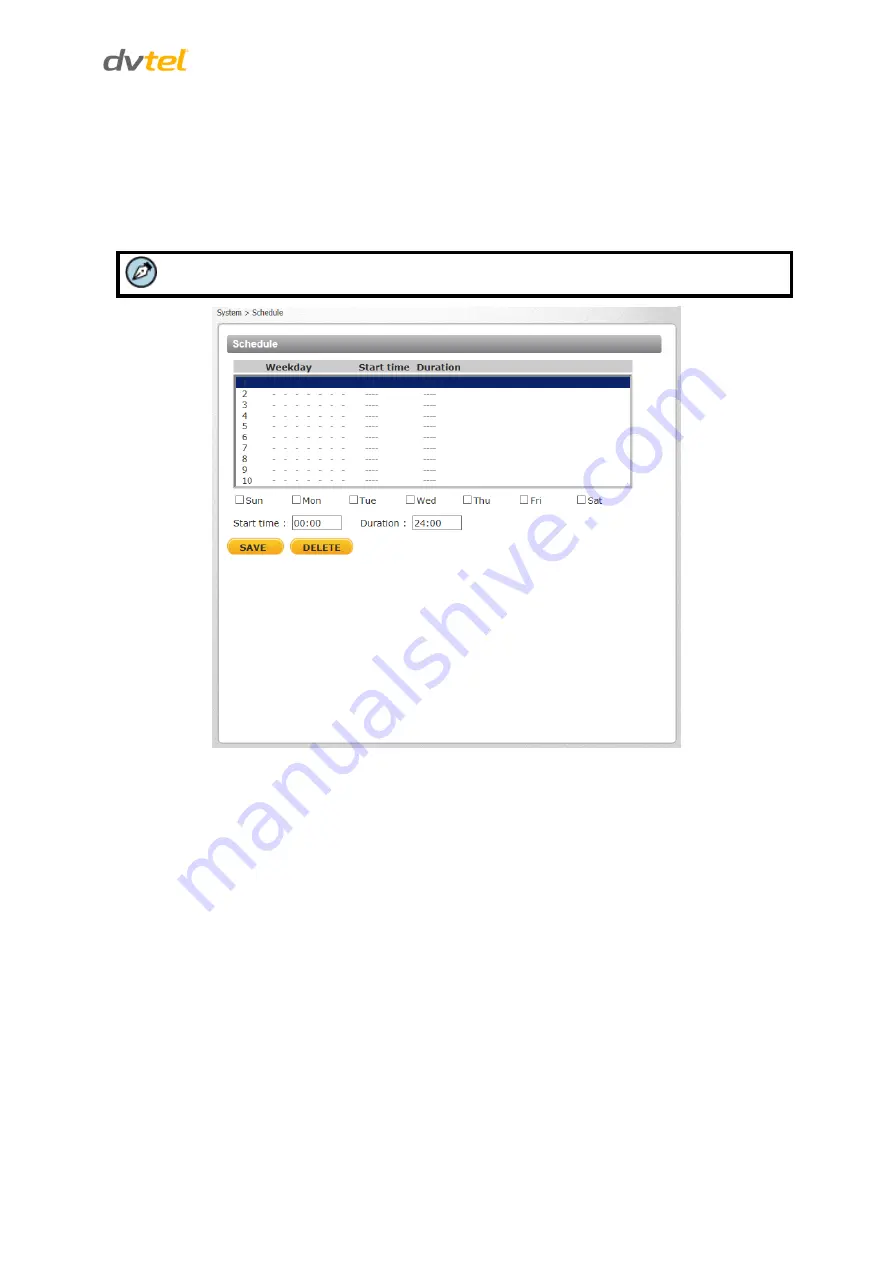
available dropdown. See Figure 74: Schedule Screen. 


Note:  

This application is not the same as the Recording Schedule function.  


Figure 74: Schedule Screen 

To create a new schedule or edit an existing schedule 

1.


Select the appropriate checkbox for the day(s) of the week (Sun, Mon, Tue, Wed, Thu, Fri 
and Sat) to create a schedule.  

2.


Set 

Start time

 (for example, 09:00) and 

Duration

 (for example, 4:00 hours). 

3.


Click 

SAVE

 to apply the newly created schedule to the camera. 

To remove a schedule 

1.


To remove a schedule, select the setup data line by line. 

2.


Click 

DELETE 

to remove. 

Summary of Contents for CB-6204

Page 1: ...mera User and Installation Guide Rev 03 March 12 2015 DVTEL INC 65 Challenger Road Ridgefield Park NJ 07660 The contents of this guide may not be reproduced or reprinted in whole or in part without th...

Page 2: ...lation 13 5 1 Indoor Installation 13 5 2 Outdoor Installation 13 5 3 Power and Ethernet Cable Connection 14 5 4 Initial Camera Configuration 14 5 5 Mounting Instructions 15 5 5 1 Eliminating IR Reflec...

Page 3: ...6 Video Mask 101 9 4 7 Audio 102 9 5 Camera Settings 103 9 5 1 Exposure 104 9 5 2 Picture Adjustment 112 9 5 3 Advanced Picture Settings 113 9 5 4 IR Function 117 9 5 5 Miscellaneous 119 9 6 Log Out...

Page 4: ...e 26 Live View Screen 29 Figure 27 Live Video Info Dialog Box 29 Figure 28 System Section Tabs 31 Figure 29 System Screen 32 Figure 30 User Screen 33 Figure 31 Edit User Account Dialog Box 34 Figure 3...

Page 5: ...n 85 Figure 86 File Download Screen 85 Figure 87 Streaming Section Tabs 86 Figure 88 CB 6204 Video Format Screen 87 Figure 89 CB 6208 Video Format Screen 88 Figure 90 View 1 Source 94 Figure 91 View 2...

Page 6: ...y or death Avertissement est un message pr ventif indiquant qu une proc dure ou condition pr sente un risque potentiel de blessure ou de mort A Caution is a precautionary message that indicates a proc...

Page 7: ...consignes de s curit les normes et les codes lectriques ainsi que la l gislation en vigueur sur le lieu d implantation des unit s Proprietary Rights and Non Disclosure This manual is delivered subjec...

Page 8: ...adapt s l usage auquel l utilisateur les destine DVTEL Inc ne pourra tre tenu pour responsable en cas de mauvaise utilisation ou de mise en place de mesures de s curit insuffisantes Le non respect de...

Page 9: ...p reduce risk of injury or damage observe the following Pr cautions et avertissements d ordre g n ral Cette section contient des informations indiquant qu une proc dure ou condition pr sente des risqu...

Page 10: ...cam ra et ne retirez pas ses vis Aucune pi ce se trouvant l int rieur de l unit ne n cessite un entretien par l utilisateur 4 Seul un technicien form et qualifi est autoris entretenir et r parer cet...

Page 11: ...d ground conductor 5 If you use an extension cord with this system make sure that the total ampere rating on the products plugged into the extension cord does not exceed the extension cord ampere rati...

Page 12: ...nge avec ce syst me assurez vous que l amp rage total des produits branch s sur la rallonge ne d passe pas l amp rage nominal de celle ci 6 Pour viter tout risque de choc lectrique ou d endommager l u...

Page 13: ...ld allow easy access to unit connections and cables Safety Cables and electrical cords should be routed in a manner that prevents safety hazards such as from tripping wire fraying overheating etc Ensu...

Page 14: ...g four simultaneous video streams at UHD 2160p Full HD 1080p HD 720p and D1 resolutions The family consists of two cameras with a varifocal motorized auto focus F1 4 P Iris lens with True Day Night an...

Page 15: ...pport up to two servers Send images on alarm to e mail E mail SMTP alarm notification up to two e mails 128GB microSDXC recording support Record snapshots to microSDXC card on alarm Sequential snapsho...

Page 16: ...r x5 M4 Self Tapping Screw x5 CD Bundled software and documentation Quick Installation Guide Desiccant User and Installation Guide Figure 1 Package Contents Note The self tapping screws are mainly for...

Page 17: ...n The connectors included on the camera s system cable are described Typical CB 620x Camera Camera Dimensions Internal Connectors System Cable Connectors 3 1 Typical CB 620x Camera The figure below sh...

Page 18: ...e To perform a hard reset to full factory defaults using the Reset button 1 Press a pointed object against the black switch on the Reset button 2 Press the button for 30 seconds Both LEDs on the RJ45...

Page 19: ...alog video output 3 4 1 Waterproofing the Camera Cable Connectors Follow the instructions below to waterproof the connectors for the different types of cables included in the system cable The cables a...

Page 20: ...1 Plug the Ethernet cable to the connector of the RJ45 cable Figure 9 RJ45 Connector and Plug 2 Coat the joint with silicone gel Make sure there is no gap between the Ethernet cable and the connector...

Page 21: ...ission quality cable length should not exceed 100 meters 328 feet Connect one end of the Ethernet cable to the RJ45 connector of the system cable and plug the other end of the cable to the network swi...

Page 22: ...Introduction to the CB 620x IP Bullet Camera 9 3 4 4 Input and Output Connectors The alarm input and output connectors are shown below Pin No Designation 1 Input 2 Input 3 Output 4 Output...

Page 23: ......

Page 24: ...ow Item Minimum System Requirement Personal Computer Minimum Intel Core i5 2430M 2 4 GHz 4GB RAM Recommended Intel Core i7 870 2 93 GHz 8GB RAM Operating System Windows XP Windows 7 Windows 8 Windows...

Page 25: ......

Page 26: ...he camera on or near radiators and heat sources All electrical work must be performed in accordance with local regulatory requirements 5 2 Outdoor Installation Read the instructions provided in this c...

Page 27: ...device such as a switch 4 Verify that the LEDs on the RJ45 connector illuminate green indicating a stable network connection and flashing yellow to indicate network activity 5 Do the following a Copy...

Page 28: ...ty Pinpoint can be used to connect a laptop directly to the camera when using PoE 5 5 Mounting Instructions The camera can be installed directly on a wall or ceiling with the integrated three axis adj...

Page 29: ...e system cable through the mounting accessory Note The power cable is not required if using PoE Tip Even if you are not using alarm inputs and audio input output at the time of installation you may wa...

Page 30: ...ameter 15 mm 0 6 radius 5 Drill the cable entry hole 6 Drill a hole slightly smaller than the supplied plastic screw anchor on each marked screw hole 7 Insert the plastic screw anchors into the drille...

Page 31: ...o screws circled in the picture below in order to manipulate the camera positioning at the ball joint The camera can be twisted and moved up and down at the ball joint Figure 18 Repositioning the Came...

Page 32: ...essible over the network Once listed each camera can be right clicked to access and change the network settings If the network settings are changed for some reason a new search will relist the units T...

Page 33: ......

Page 34: ...DNA icon Note DNA is an alternative software to Device Search Either of these programs may be used 3 In the DNA application click the DNA button 4 If the Windows Firewall is enabled a security alert...

Page 35: ...tude i Select Use DHCP Do not use for Latitude ii Click Update and wait for status b For Static IP recommended for Latitude users Figure 22 DNA Assign IP Static IP Dialog Box i Do not select the Use D...

Page 36: ...ght click the Information Bar Select Install ActiveX Control to allow the installation Figure 23 Installing the ActiveX Control If a security warning window prompt appears click Install Figure 24 Secu...

Page 37: ......

Page 38: ...default user name Admin and password 1234 If the password has previously been changed use the new password Note Both the user name and password are case sensitive b Allow the ActiveX to download and...

Page 39: ......

Page 40: ...e described in detail Additionally if DVTEL s Latitude VMS is used many of the configurations and features of DVTEL s VMS provide configuration and automation of the camera This section includes the f...

Page 41: ...ministrator can modify video and audio settings on this page Details are discussed in Streaming Settings Camera Settings The administrator can adjust many of the camera settings on this page such as E...

Page 42: ...en includes the following function buttons Snapshot Click this button to automatically save the JPEG snapshots in the specified location The default location to save snapshots is C To change the stora...

Page 43: ...Click the Speaker button to mute activate the audio This function is available only to a user who has been granted this privilege by the Administrator Refer to User in the Security section for furthe...

Page 44: ...and continuously maintains focus regardless of zoom or view changes The focus status is displayed above the Live View pane 9 3 System Settings The Settings tab in the Navigation Bar opens the section...

Page 45: ...d then specify time offset number of hours or minutes difference between daylight saving time and standard time start date and time for daylight saving time and end date and time for daylight saving t...

Page 46: ...m sidebar opens a drop down menu with the following screens User HTTPS IP Filter IEEE 802 1X 9 3 2 1 User Click the User tab in the Security category on the sidebar to display user credentials Figure...

Page 47: ...ame drop down list and select the user Click DELETE to remove the user To edit a user click the User name drop down list and select the user Click EDIT to edit the user s password and privileges Note...

Page 48: ...CA issued certificate HTTPS allows secure connections between the camera and web browser using Secure Socket Layer SSL or Transport Layer Security TLS to protect camera settings and username password...

Page 49: ...Enter the local administrative region Locality Enter other geographical information Organization Enter the name of the organization to which the entity identified in Common Name belongs Organizational...

Page 50: ...roperties dialog box If you want to remove the certificate click REMOVE Figure 35 Certificate Properties 5 When the signed certificate is returned from the CA click Browse in the Install Signed Certif...

Page 51: ...quest 1 Click CREATE CERTIFICATE REQUEST to create and submit a certificate request in order to obtain a signed certificate from a CA Figure 37 HTTPS Screen Install Signed Certificate The Create Certi...

Page 52: ...rganizational Unit Enter the name of the organizational unit to which the entity identified in the Common Name field belongs Common Name Indicate the name of the person or other entity that the certif...

Page 53: ...ollowing page Figure 41 IP Filter Screen To enable the IP filter 1 Check the box to enable the IP filter function Once enabled the listed IP addresses IPv4 are allowed or denied access to the camera 2...

Page 54: ...ertificate to check the server s identity Client Certificate Upload the Client Certificate to authenticate the camera Click Browse to locate the file and UPLOAD to upload the certificate Private Key U...

Page 55: ...ings Figure 43 Network Basic Screen It is possible to connect to the camera with either fixed or dynamic DHCP IP address The camera also provides PPPoE Point to Point Protocol over Ethernet support fo...

Page 56: ...ts to fail Primary DNS The primary domain name server that translates host names into IP addresses Secondary DNS A secondary domain name server that backs up the primary DNS Use PPPoE To use PPPoE 1 E...

Page 57: ...rked with DSCP DiffServ Code point values and as a result receive the corresponding forwarding treatment from DiffServ capable routers DSCP configuration settings are entered in the System Network QOS...

Page 58: ...pecify the community name that has read only access to all supported SNMP objects The default value is public Write Community Specify the community name that has read write access to all supported SNM...

Page 59: ...note below Note You may have to consult with your System Administrator to activate this function Traps for SNMP v1 v2 v3 Traps are used by the camera to send messages to a management system for import...

Page 60: ...UPnP If UPnP is enabled and a camera is discovered on the LAN the icon of the connected camera appears in My Network Places allowing direct access as seen below Figure 47 Direct Access to Camera with...

Page 61: ...stantly synchronized with a dynamic IP address This permits those using a dynamic IP address to be accessed by a static domain name DDNS configuration settings are entered in the System Network DDNS s...

Page 62: ...l server configuration settings are entered in the System Network Mail screen Figure 49 Mail Screen SMTP Two SMTP server accounts can be configured with or without SSL encryption Enter the settings fo...

Page 63: ...n passive mode FTP the client initiates both connections to the server solving the problem of firewalls filtering the incoming data port connection to the client from the server In order to support pa...

Page 64: ...ification checkbox on the IO Tampering Manual trigger and Motion Detection screens Two notification server accounts Alarm Triggered and Motion Detection can be set up and sent to the specified HTTP se...

Page 65: ...generated when an event is recognized by the system Figure 52 IO Screen 9 3 4 1 1 Alarm Switch The Administrator can select from the following options Select Off to disable an alarm Select On to enab...

Page 66: ...e designated FTP site Note Images can be sent by FTP only when MJPEG is selected as the video stream from the Video Format screen Follow these steps From the FTP address drop down list select one of t...

Page 67: ...by E Mail Select the checkbox send an alarm message by e mail when an alarm is triggered The e mail address is entered in the Mail screen Upload image by E Mail Select this checkbox to assign an e mai...

Page 68: ...your requirements Add date time suffix default setting File name imageYYMMDD_HHNNSS_XX jpg Y Year M Month D Day H Hour N Minute S Second X Sequence Number Add sequence number suffix no maximum value...

Page 69: ...e to a network failure Figure 57 Network Failure Detection Screen 9 3 4 2 1 Detection Switch The Administrator can select from the following options Select Off to disable an alarm default setting Sele...

Page 70: ...second radial button to upload during the active trigger See Figure 55 Record Video Clip Note In order for this function to be implemented make sure that local recording with a microSDXC card is acti...

Page 71: ...ype of alarm output high or low to enable alarm relay when tampering is detected Send Message by FTP The Administrator can select whether to send an alarm message by FTP when tampering is detected Upl...

Page 72: ...t screen Select one of two e mail addresses from the drop down menu Select the number of frames for the pre trigger and post trigger buffers from the drop down menu of 1 20 frames Check the box for Co...

Page 73: ...e which is set on the IR Function screen Figure 59 Day Night Trigger Screen In the Day Night Trigger section select On to enable the Day Night Trigger or Off to disable it In the Day Night Type sectio...

Page 74: ...red Action The Administrator can specify multiple alarm actions to be taken when a triggering event occurs The options are listed as follows Upload Image by FTP Selecting this option enables you to as...

Page 75: ...the Mail and FTP sections for further details 9 3 4 5 4 File Name File Name Enter a file name in the field for example image jpg The uploaded image s file name format is set in this section Select one...

Page 76: ...r to send an alarm message by FTP when an alarm is triggered Upload Image by FTP Selecting this option enables you to assign an FTP site and configure various parameters as seen in Figure 53 Upload Im...

Page 77: ...n menu Select the number of frames for the pre trigger and post trigger buffers from the drop down menu of 1 20 frames Check the box for Continue image upload if you wish to use this option To specify...

Page 78: ...be overwritten by the new uploaded file with a static filename Click SAVE after configuring the settings 9 3 5 Edge Recording From the Edge Recording tab it is possible to configure the following scre...

Page 79: ...finished Recording List Each video file on the microSDXC card is listed in the Recording List table below The maximum file size is 60 MB per file See Recording for further details When the recording...

Page 80: ...er or download it to a specified location Figure 64 Selected File Window 9 3 5 2 Network Share The Network Share screen shows the capacity information of the Network Attached Storage NAS disk and prov...

Page 81: ...e NAS Disk Cleanup Setting Enable automatic recording cleanup by selecting Enable automatic disk cleanup From the pull down menu specify the minimum length of time over which to remove recordings For...

Page 82: ...dow pops up as shown below Click the AVI file to play the video in the player or download it to a specified location Figure 67 Selected File Window 9 3 5 3 Recording The Recording screen is used to se...

Page 83: ...s function Only during time frame Records only during a specified time frame Figure 68 Recording Screen To set the recording schedule 1 Selecting the day 2 Set the start time 3 Set the duration for re...

Page 84: ...t outward or inward Moving the mouse to the center of the frame shifts the frame to the intended location Motion Detection Activation It is possible to define up to four motion detection zones within...

Page 85: ...n Detection Screen with Schedule Drop Down Menu Motion Detection Windows Up to 10 Motion Detection windows can be set Click the ADD button under the Live View pane to add a Motion Detection window To...

Page 86: ...otion indication window will be lowered accordingly Time interval sec 0 7200 Select a number from 0 7200 seconds The default interval is 10 The value is the interval between each detected motion Trigg...

Page 87: ...ers See Figure 54 Send HTTP Notification Send alarm message by E Mail Select whether to send an alarm message by e mail when motion is detected Note Make sure that local recording with a microSDXC car...

Page 88: ...that schedule to this camera using the available dropdown See Figure 74 Schedule Screen Note This application is not the same as the Recording Schedule function Figure 74 Schedule Screen To create a n...

Page 89: ...ion page specify a storage location for snapshots and web recordings The default setting is C After confirming the setting click SAVE to save the snapshots and recordings in the designated location Fi...

Page 90: ...ens a drop down menu with the following tabs Log File User Information Factory Default Software Version Software Upgrade Parameters 9 3 9 1 Log File Click Log file to view the system log file The cont...

Page 91: ...the User information screen shown below Note User credentials and privileges are set in the User screen page 33 View User Login Information Click GET USER INFORMATION to see each user s details For e...

Page 92: ...k GET USER PRIVACY to view each user s privileges Figure 78 User Information Get User Privacy In the screen above both Admin and User are granted privileges of I O access Camera control Talk and Liste...

Page 93: ...elow Follow the instructions to reset the camera to factory default settings if needed Figure 79 Factory Default Screen Full Restore Click FULL RESTORE to restore the factory default settings The syst...

Page 94: ...store Click PARTIAL RESTORE to restore the factory default settings but save the network settings The system restarts in 30 seconds Figure 80 Partial Restore Screen Reboot Click REBOOT to restart the...

Page 95: ...4 Software Version The current version of the software is displayed in the Software Version screen Figure 81 Software Version Screen 9 3 9 5 Software Upgrade The Software Upgrade screen enables you t...

Page 96: ...mage userland img is selected 3 Click UPGRADE The system verifies that the upgrade file exists and begins to upload the file The upgrade status bar is displayed on the page When the upgrade process is...

Page 97: ...nstallation Guide 84 9 3 9 6 Parameters The Parameters screen displays all of the system s parameter settings Figure 84 Parameter Screen Note Slide the sidebar located on the right of the screen to vi...

Page 98: ...popup window File Download appears as shown below Figure 86 File Download Screen Click Save and specify a location to save the configuration file Warning Do not unplug power while changing file names...

Page 99: ...udio selections in the sidebar From the Streaming sidebar the Administrator can configure a specific video resolution video compression mode video protocol audio transmission mode etc Details of these...

Page 100: ...at From the Video Format screen you can configure the following settings Video Resolution Settings Text Overlay Settings Video Rotate Type GOV Settings H 264 Profile CB 6204 cameras support three vide...

Page 101: ...deo Resolution Settings The following video resolutions are supported H 264 Only MJPEG Only H 264 H 264 and H 264 MJPEG H 264 H 264 H 264 and H 264 H 264 MJPEG 9 4 1 1 1 H 264 Only H 264 Only TV Syste...

Page 102: ...WDR2 3 1280 x 720 25 30 fps 1280 x 720 25 30 fps NA 720 x 576 25 fps 720 x 480 30 fps WDR2 3 720 x 576 25 fps 720 x 480 30 fps 720 x 576 25 fps 720 x 480 30 fps NA 9 4 1 1 4 H 264 H 264 H 264 and H 26...

Page 103: ...x 720 60 fps Y 720 x 576 25 fps 720 x 480 30 fps 720 x 576 50 fps 720 x 480 60 fps Y 9 4 1 2 2 MJPEG Only MJPEG Only PAL 25 FPS NTSC 30 FPS PAL 50 FPS NTSC 60 FPS BNC Support 1920 x 1080 25 fps 1920...

Page 104: ...50 fps 1280 x 720 50 fps N 720 x 576 50 fps Y 720 x 576 50 fps 720 x 576 50 fps Y H 264 H 264 MJPEG NTSC 60 FPS Stream 1 Stream 2 BNC Support 1920 x 1080 60 fps 1280 x 720 60 fps N 720 x 480 60 fps Y...

Page 105: ...1 Stream 2 Stream 3 1920 x 1080 60 fps 1280 x 720 60 fps 720 x 480 60 fps 720 x 480 60 fps 1280 x 720 60 fps 1280 x 720 60 fps 720 x 480 60 fps 720 x 480 60 fps 720 x 480 60 fps 720 x 480 60 fps 720...

Page 106: ...20 x 576 50 fps 720 x 576 50 fps 720 x 576 50 fps 720 x 576 50 fps 720 x 576 50 fps 1280 x 720 50 fps 1280 x 720 50 fps 1280 x 720 50 fps 720 x 576 50 fps 720 x 576 50 fps 720 x 576 50 fps 720 x 576 5...

Page 107: ...Figure 90 View 1 Source To rotate the image vertically for example select Flip video The displayed image is reversed as shown below Figure 91 View 2 Image Rotated Vertically Reversed Following are des...

Page 108: ...uire additional data loss robustness Baseline Profile is used in some videoconferencing and mobile applications This is the most common profile used in IP security cameras due to the low computational...

Page 109: ...er and Installation Guide 96 9 4 2 Video Compression From the Video Compression page you can specify MJPEG and H 264 compression settings CB 6204 cameras support three video streams Figure 92 CB 6204...

Page 110: ...ault setting of H 264 1 is 4096 The default setting for the other streams is 1024 kbps Each stream can be configured individually The setting range is from 64 to 20 480 kbps Click SAVE to confirm the...

Page 111: ...important zones in the scene Figure 94 Video ROI Encoding Screen To use ROI encoding 1 From the Video Stream drop down menu select the H 264 stream Three streams are available on CB 6204 cameras Four...

Page 112: ...available on CB 6208 cameras Figure 95 Video OCX Protocol Screen Video OCX protocol setting options include RTP over UDP RTP over RTSP TCP RTSP over HTTP MJPEG over HTTP Multicast mode Enter in each f...

Page 113: ...the MJPEG Frame Rate is from 1 to 60 in NTSC and 1 to 50 in PAL The default setting is 30 fps in NTSC and 25 fps in PAL H 264 1 The setting range for the H 264 1 Frame Rate is from 1 to 15 in NTSC and...

Page 114: ...ocked out or obscured from view To enable a mask 1 Check a Video Mask checkbox A red frame is displayed in the Live Video pane on the right side 2 Use the mouse to drag and drop adjust the mask s size...

Page 115: ...e at one time Simplex Talk only In the Talk only Simplex mode the local remote site can only talk to the other site Simplex Listen only In the Listen only Simplex mode the local remote site can only l...

Page 116: ...isabled in the Audio screen The default setting is Disabled Note This function works only if the Recording to Storage option has been selected or if the Schedule option has been set Click SAVE to conf...

Page 117: ...Near or Far Step button to alternate the focus between near and far views within a user defined range which can be selected from the drop down menu AF Click the Push AF button once to adjust zoom or f...

Page 118: ...5 1 1 CB 6204 Exposure Screen The bottom section of the screen enables you to select one of three exposure modes P Iris Priority Auto P Iris default or Manual Mode Administrators may either allow the...

Page 119: ...osure Auto Adjustment From the drop down menu select On or Off When enabled if the lighting level falls below the set P iris level the iris will jump to its fully opened position Min Shutter Speed Whe...

Page 120: ...isplays the current F Stop setting Click SET when you finish configuring the settings Manual Mode Manual Mode opens the iris completely with a fixed gain to a fixed shutter speed Users can select a su...

Page 121: ...5 1 30 1 12 1 15 1 6 1 8 1 3 1 4 Gain A nominal video signal level is usually 1 volt peak to peak for composite video 0 7 volts for component or RGB video or 0 3 volts for the chrominance subsection a...

Page 122: ...Shutter Speed When selecting this mode the shutter is completely open and the exposure priority is given to the iris Shutter speed and AGC circuit function automatically in cooperating with the iris...

Page 123: ...ll the options Auto Shutter Min Shutter speed PAL NTSC 1 425 1 500 1 300 1 350 1 215 1 250 1 150 1 180 1 120 1 120 1 100 1 100 1 75 1 90 1 50 1 60 1 25 1 30 1 12 1 15 1 6 1 8 1 3 1 4 1 1 5 1 2 1 Shutt...

Page 124: ...100 1 75 1 90 1 50 1 60 1 25 1 30 1 12 1 15 1 6 1 8 1 3 1 4 1 1 5 1 2 1 Click SET when you finish setting the shutter speed Gain A nominal video signal level is usually 1 volt peak to peak for composi...

Page 125: ...tness by adjusting this parameter Select from the range between 12 to 13 To increase video brightness select a larger number Click SET to confirm the new setting 9 5 2 2 Sharpness Increasing the sharp...

Page 126: ...A camera needs to find a reference color temperature as a way of measuring the quality of a light source for calculating all other colors The unit for measuring this ratio is in Kelvin K degrees You...

Page 127: ...ironment with a light source color temperature in the range of approximately 2500 10 000K One Push This button activates the factory optimized setting for white balance This setting may not be ideal f...

Page 128: ...implemented by using a combination of slow and fast exposure shutters The camera uses an algorithm to determine the optimal mix of light and dark regions within the scene from the two shutters in orde...

Page 129: ...n blur and provides clear images even in low light environment The combination of SPQ and 3DNR at different levels further yields exceptional video performance in various conditions The Noise Reductio...

Page 130: ...llowing is an explanation of the four settings Auto Mode The camera converts from Day mode color to Night mode monochrome automatically at nighttime or in low light conditions When there is sufficient...

Page 131: ...ction For the daytime to nighttime threshold from the upper drop down list select a number between 1 9 where 1 is darker and 9 is brighter For the nighttime to daytime threshold from the upper drop do...

Page 132: ...t s IP address again in your browser in order to use the unit with the new settings 9 5 5 2 1 CB 6204 TV System Settings Select one of two WDR settings according to your TV standard WDR 2 shutter NTSC...

Page 133: ...e video system and WDR setting according to the desired frame rate and the TV standard 25 fps PAL 30 fps NTSC 50 fps PAL or 60 fps NTSC 9 6 Log Out Selecting the Logout link on the Home page to close...

Page 134: ...chnical Specifications CB 6208 Technical Specifications Device Search Software Internet Security Settings Install UPnP Components Deleting Existing DVPlayer Deleting Temporary Internet Files Connectin...

Page 135: ...g Maximum Performance H 264 25 30 fps PAL NTSC QHD or simultaneous QHD 12 15 fps HD 720p 12 15 fps D1 12 15 fps PAL NTSC Rate Control Option CBR 64Kbps 20 480Kbps VBR Operation Image Setting Brightnes...

Page 136: ...nator Working Distance 40 meters 131 ft at 60 Wavelength 850nm IR Sensitivity Yes 680 1100nm LEDs 6 Network Interface 10 100 1000Mbps Ethernet Auto sensing Full Half Duplex Protocols IPv4 v6 TCP IP UD...

Page 137: ...kg 2 36 lbs Electrical Power Consumption Indoor 6W Outdoor 13W with heater and IR Power Source 12VDC 10 24VAC 10 PoE 802 3af Class 0 Environmental Operating Temperature 40 to 50 C 40 to 122 F with hea...

Page 138: ...s PAL NTSC 4K or simultaneous 4K 12 15 fps Full HD 1080p 12 15 fps HD 720p 12 15 fps D1 12 15 fps PAL NTSC Rate Control Option CBR 64Kbps 20 480Kbps VBR Operation Image Setting Brightness Manual Expos...

Page 139: ...ts in Latitude IR Illuminator Working Distance 40 meters 131 ft at 60 Wavelength 850nm LEDs 6 Network Interface 10 100 1000Mbps Ethernet Auto sensing Full Half Duplex Protocols IPv4 v6 TCP IP UDP RTP...

Page 140: ...10 PoE 802 3af Class 0 Environmental Operating Temperature 40 to 50 C 40 to 122 F with heater 25 C to 50 C 13 to 122 F for cold start with POE Humidity 10 95 non condensing General Regulatory US FCC...

Page 141: ...d Bar toolbar select Tools and select Internet Options from the menu that appears Figure 111 Command Bar Toolbar Select Internet Options 3 In the Internet Options window that appears select the Securi...

Page 142: ...In the dialog that appears under ActiveX controls and plug ins set ALL the following options listed below to Enable or Prompt Automatic prompting for ActiveX controls Binary and script behaviors Downl...

Page 143: ...below to enable UPnP so that the camera can be discovered and displayed in Network locations under Other Devices To enable UPnP discovery in Windows 7 8 and 8 1 1 Click Start and select Control Panel...

Page 144: ...h Windows Firewall and that other firewalls are not interfering with network discovery To check that the UPnP Device Host services are running 1 Click Start and type in the Search programs and files f...

Page 145: ...e PC should first delete the existing DVPlayer from the PC before accessing the camera To delete a legacy DVPlayer 1 Click Start and select Control Panel 2 In the Control Panel click Uninstall a progr...

Page 146: ...delete temporary Internet files 1 In Internet Explorer IE from the Command Bar toolbar click Tools and select Internet Options from the menu that appears 2 In the General tab in the Internet Options d...

Page 147: ...m DVTEL for installation of your Quasar Gen II CB 6204 Series Bullet IP Camera For more information on available options contact your DVTEL sales representative or visit www DVTEL com to request detai...

Page 148: ...61 8 8235 9255 info anz DVTEL com EMEA DVTEL UK Ltd 7 Lancaster Court Coronation Road High Wycombe HP12 3TD England Tel 44 0 1494 412240 Fax 44 0 1494 446928 info uk DVTEL com INDIA AND SAARC GULF RE...

Reviews: