


Model 9113-1-X Product Manual
Page 9
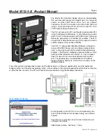
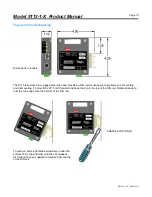
9113 Power-up:
Power-up with DIP Switch 4 off...
When power is applied to the 9113 it will begin looking for an active ethernet network. During this time the Mode
LED and Fault LED will be lit steady red and remain that way until an active network is detected. Once an active
network is detected the Fault LED will turn off. If switch two is on (DHCP Mode) then the Mode LED will begin
flashing red indicating it is requesting an IP address. Once the IP Address Server provides an address the Mode
LED will begin flashing amber indicating it is ready to receive network requests from a PLC, Ultraware
software, or the Web Utilities browser. If switch two is off the assigned IP address is used and the Mode LED
begins flashing amber while the Fault LED is turned off.
Power-up with DIP Switch 4 on...
This is firmware update mode. When power is applied to the 9113 and it will begin looking for an active ethernet
network. During this time all LEDs will be off. Once an active network is detected the Mode LED will begin
flashing red. Firmware update always uses DHCP mode. Refer to the Firmware Update topic for a description
of the subsequent LED activity you can expect to see.
Internal Fault Register:
The internal fault register consists of sixteen bits and may be accessed by the PLC as B010:038. The bits
indicate individual errors or faults that are recognized by the 9113 and are listed in the table below. The Web
Utilities program can be used to allow the PLC to reset the fault and/or set a time period for fault reset.
Bit Number
Fault Description
Bit Number
Fault Description
0
Invalid file type request
1
Invalid byte count request
2
Invalid file or element request
3
Invalid read/write function code
4
Invalid word number request
5
Open session failure
6
Ultraware access failure
7
Test mode running
8
Serial port bad reply
9
Serial port exception returned
10
Math fault
11
Serial port CTS failure
12
Serial port - No reply
13
Not assigned
14
Global Index Selector Fault
15
Fail safe
Refer to the 9113-1-X help file for additional information about the Fault Register. The help is available in the
free configuration software of online at
www.QuartechCorp.com.
PM 9113-1-X R evision 0