

www.quark-elec.com
Page 2 of 3
2017
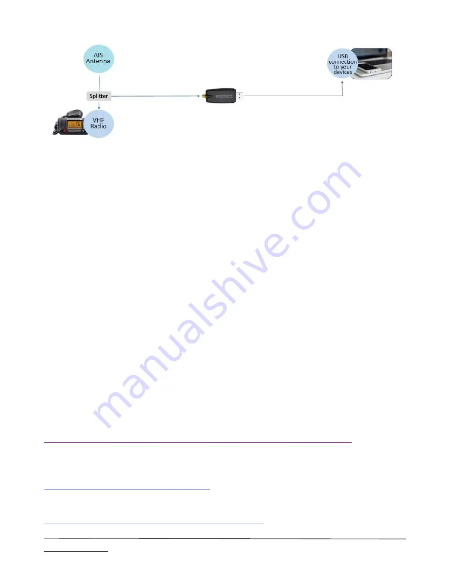
CONNECTIONS
QK-A021 has the following electrical connections/indicators:
AIS antenna connector
. Standard SMA female 50 Ohm connector. An active VHF antenna splitter is
required if one VHF antenna is shared by QK-A021 and VHF voice radio. (We recommend separate
antennas ideally.)
USB connector
. A USB connector outputs the AIS messages directly to the connected device. It
can also be used for adjusting hopping parameters using the GUI Configuration software.
Check the LED lights
. QK-A021 features two LEDs fitted inside the case which indicate power (red)
and AIS messages received (green). The red LED should be permanently on, the green AIS LED will flicker
at a fast rate when signals are received.
POWER UP
QK-A021 is designed to be powered through the USB connection.
CONFIGURATION
The module can be configured using the Quark-elec
GUI Configuration Application
(See below download
link) which is free to download and very straightforward. This enables the operator to specify hopping
intervals of 1s, 30s and .25s according to preference and need. Our patented algorithm is likely to pick up
more messages, faster than the manual settings but there are certain environments and locations where
manual setting may be desirable. An article is available explaining this is on our blog:
https://www.quark-elec.com/blog/2017/12/20/latest-field-test-of-patented-autohopping-algorithm/
The Configuration Software (GUI) can be used to adjust these settings, including baud rates and WiFi
settings. You can download the software here:
https://quark-elec.com/doc/QE_MUX_configTool.zip
Detailed instructions on how to use the Configuration software are available here:
https://www.quark-elec.com/doc/QK-A0xx_GUI_application_note.pdf


