background image

Chapter 1  Library Description

Library Components

Quantum P4000 and P7000 Libraries User’s Guide

25

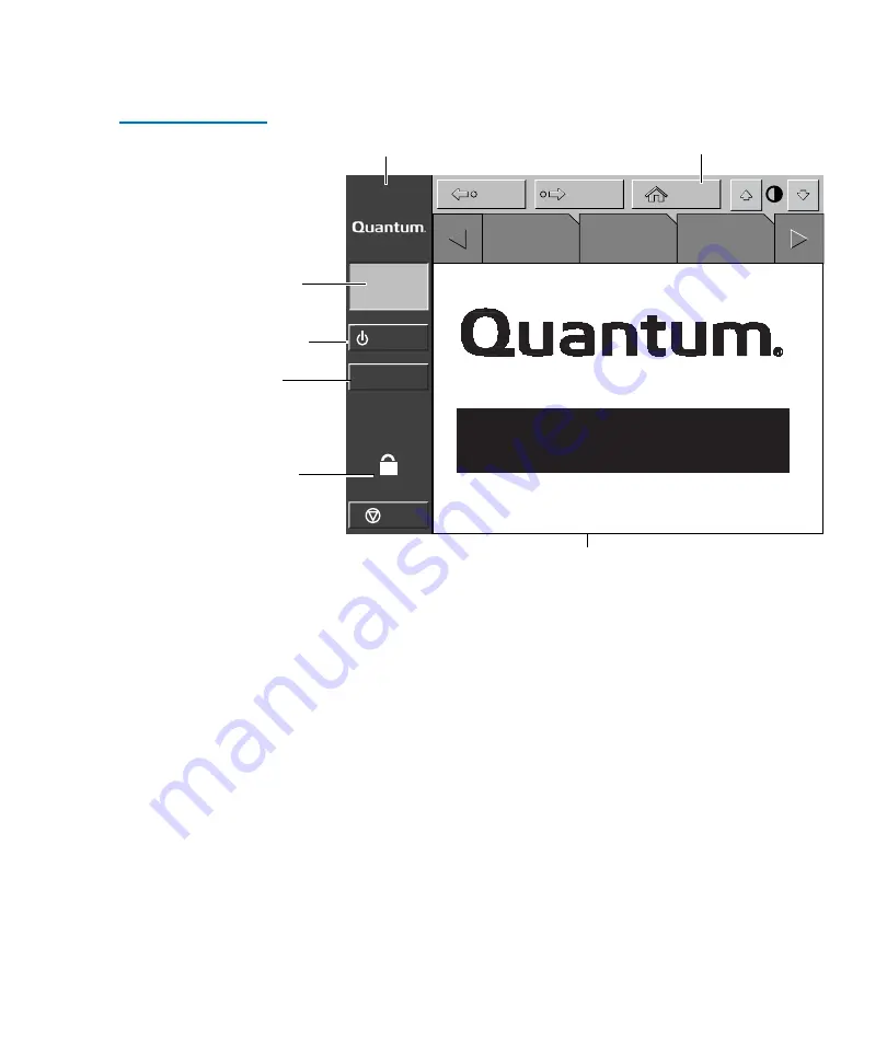
Figure 13  GUI—Initial 
Screen (P7000)

The horizontal taskbar provides left and right arrow buttons to scroll 

through the tabs for status, configuration, diagnostic, and operating 

controls options. 
The vertical taskbar provides various library controls:
• System state display - indicates current tasks and requests in process.
• Standby - takes the library “off-line” or “on-line”.
• Load port button - submits request to the library to open the load 

port.

• Security level indicator - shows “locked” on start-up and 

initialization (default).

• Stop button - immediately removes power from the library robotics.

Load Port

System
Off-line

Standby

Overview

Tapes

Operator

Back

Forward

Home

U

Stop

About

P 7 0 0 0

Horizontal

task bar

Vertical

task bar

Main display area

System
state
display

Security
indicator/

Standby

Load
port

switch

Summary of Contents for P4000 Series

Page 1: ...Quantum P4000 and P7000 Libraries User s Guide 6434003 04 Ver 4 Rel 0...

Page 2: ...time to time without notice COPYRIGHT STATEMENT Copyright 2004 by Quantum Corporation All rights reserved Your right to copy this manual is limited by copyright law Making copies or adaptations withou...

Page 3: ...Numbering Conventions 5 Features and Benefits 19 Library Components 20 Cabinet 20 GUI 24 IntelliGripTM Mixed Media CHM 26 Tape Drives 27 Load Port and Magazines 28 Chapter 2 Basic Library Operations...

Page 4: ...w Screen 48 Tapes Screen 51 Changing the GUI Security Levels 52 Securing the GUI 53 Operating the Load Port 54 Loading a Tape Cartridge Magazine 55 Inserting Tape Cartridges into the Load Port 55 Inse...

Page 5: ...on 83 Executing Either Command 83 Chapter 5 Multi Unit Commands 85 Opening the Multi Unit Screen 86 Configure Multi Units P4000 P7000 87 Calibrating the Libraries in a Multi Unit Configuration 89 Chap...

Page 6: ...matic Drive Cleaning 117 Drive Cleaning Modes 117 Host Initiated Cleaning Mode 117 Automatic Drive Cleaning Mode 118 Selection of Cleaning Mode 118 Diagnostic Software 118 GUI 119 Mode Select Command...

Page 7: ...Contents vii Quantum P4000 and P7000 Libraries User s Guide Appendix E Regulatory Statements 129 Glossary 137 Index 143...

Page 8: ...Contents Quantum P4000 and P7000 Libraries User s Guide viii...

Page 9: ...gure 6 Bin Shelf Numbering Conventions P7000 16 399 14 Figure 7 Bin Shelf Numbering Conventions P7000 16 555 16 Figure 8 Bin Shelf Numbering Conventions P7000 8 679 18 Figure 9 P4000 Cabinet Front Vie...

Page 10: ...ng the Load Port Drum 57 Figure 32 LTO Tape Cartridge Load Port 58 Figure 33 DLT Tape Drive Front Bezel Example 59 Figure 34 Password Screen 62 Figure 35 Operator Screen 63 Figure 36 Configure Library...

Page 11: ...Horizontal Carriage Restraint 108 Figure 56 Pivoting Gripper Restraint into Position 109 Figure 57 Gripper Restraint in Position 109 Figure 58 Installing the Gripper Restraint 110 Figure 59 Installing...

Page 12: ...x Quantum P4000 and P7000 Libraries User s Guide...

Page 13: ...000 3 Table 7 HP LTO2 Performance Characteristics P4000 4 Table 8 DLT 8000 Performance Characteristics P7000 4 Table 9 SDLT 220 Performance Characteristics P7000 4 Table 10 SDLT 320 Performance Charac...

Page 14: ...oblems 93 Table 20 Robotics Problems 93 Table 21 Problems During Library Operation 95 Table 22 Tape Drive Problems 96 Table 23 Physical Characteristics 98 Table 24 Interfaces 100 Table 25 Performance...

Page 15: ...xiii Preface This manual introduces the Quantum P4000 and P7000 libraries and discusses Library operations Configuration Calibration Servicing Basic troubleshooting Audience This manual is written for...

Page 16: ...erator to the basic procedures for placing the library on line Chapter 3 Operator Commands describes the commands foundontheOperatorscreenoftheGUI Chapter 4 Service Commands discusses using the Servic...

Page 17: ...nent being described b All binary numbers are succeeded by b h All hexadecimal numbers are succeeded by h Error or attention conditions are represented in parenthesis that translate as follows SK S AS...

Page 18: ...can National Standard for information systems dated March 9 1990 Copies may be obtained from Global Engineering Documents 15 Inverness Way East Englewood CO 80112 800 854 7179 or 303 397 2740 Document...

Page 19: ...doc comments quantum com Quantum Home Page 0 Visit the Quantum home page at http www quantum com Customer Support 0 The Quantum Customer Support Department provides a 24 hour help desk that can be re...

Page 20: ...4000 and P7000 Libraries User s Guide Send e mail for the Customer Support Department to North South America www quantum com askaquestion Asia Pacific Rim apachelp quantum com Europe Middle East Afric...

Page 21: ...atures and benefits Library components Cabinet GraphicalUserInterface GUI IntelliGripTM mixed media cartridge handling mechanism Tape drives Mixed media load port Overview 1 The P4000 and P7000 are au...

Page 22: ...MB sec 15 MB sec 35 MB sec 30 MB sec respectively Library Models 1 The P4000 and P7000 libraries both are comprised of three models that support a wide range of storage and performance requirements a...

Page 23: ...tridge 35 42 Throughput GB hr based on 11 MB sec transfer rate 317 P4000 Model drives bins 8 322 Capacity in Terabytes TB 160 GB per cartridge 51 52 Throughput GB hr based on 16 MB sec transfer rate 4...

Page 24: ...ins 8 322 Capacity in Terabytes TB 200 GB per cartridge 64 40 Throughput GB hr based on 30 MB sec transfer rate 864 P7000 Model drives bins 16 555 Capacity in Terabytes TB 40 GB per cartridge 22 20 Th...

Page 25: ...orage bins on back wall One load port 8 shelf bins two stationary LTO load port shelf bin modules 4 shelf bins each are built into the load port assembly 12 shelf bins DLT and SDLT tape cartridges use...

Page 26: ...d P7000 Libraries User s Guide Figure 1 shows the storage bin load port bin and tape drive numbering conventions These conventions are used by the library GUI and the diagnostic software program Figur...

Page 27: ...on inside of right door 40 shelf bins on inside of left door One load port 8 shelf bins two stationary LTO load port shelf bin modules 4 shelf bins each are built into the load port assembly 12 shelf...

Page 28: ...Chapter 1 Library Description Overview 8 Quantum P4000 and P7000 Libraries User s Guide Figure 2 Bin Shelf Numbering Conventions P4000 8 322 Load port...

Page 29: ...storage bins on back wall One load port 8 shelf bins two stationary LTO load port shelf bin modules 4 shelf bins each are built into the load port assembly 12 shelf bins DLT and SDLT tape cartridges u...

Page 30: ...00 and P7000 Libraries User s Guide Figure 3 Bin Shelf Numbering Conventions P4000 10 100 P4000 10 165 Model 1 The P4000 10 165 model stores cartridges in the following locations Up to 10 tape drives...

Page 31: ...ins each are built into the load port assembly 12 shelf bins DLT and SDLT tape cartridges use two removable 6 cartridge magazines Figure 4 shows the storage bin load port bin and tape drive numbering...

Page 32: ...ns on inside of right door 40 shelf bins on inside of left door One load port 8 shelf bins two stationary LTO load port shelf bin modules 4 shelf bins each are built into the load port assembly 12 she...

Page 33: ...User s Guide 13 Figure 5 Bin Shelf Numbering Conventions P4000 10 316 P7000 16 399 Model 1 The P7000 16 399 model stores cartridges in the following locations Up to 16 tape drives 288 storage bins on...

Page 34: ...ins each are built into the load port assembly 12 shelf bins DLT and SDLT tape cartridges use two removable 6 cartridge magazines Figure 6 shows the storage bin load port bin and tape drive numbering...

Page 35: ...t door One load port 8 shelf bins two stationary LTO load port shelf bin modules 4 shelf bins each are built into the load port assembly 12 shelf bins DLT and SDLT tape cartridges use two removable 6...

Page 36: ...igure 7 Bin Shelf Numbering Conventions P7000 16 555 P7000 8 679 Model 1 The P7000 8 679 model stores cartridges in the following locations Up to 8 tape drives 372 storage bins on back wall 111 shelf...

Page 37: ...he load port assembly 12 shelf bins DLT and SDLT tape cartridges use two removable 6 cartridge magazines If the library is configured with both DLT and LTO tape drives stationary LTO load port shelf b...

Page 38: ...Chapter 1 Library Description Overview 18 Quantum P4000 and P7000 Libraries User s Guide Figure 8 Bin Shelf Numbering Conventions P7000 8 679 Load port...

Page 39: ...echnology ensures compatibility with future on board technologies such as tape drive controllers high speed host and network interfaces as well as server and tape RAID Reliable versatile 120 240 volt...

Page 40: ...ge handling mechanism CHM Storage bins Control electronics Power supply and distribution equipment Fan modules Tape drives You can access these components to monitor and control library operation thro...

Page 41: ...Chapter 1 Library Description Library Components Quantum P4000 and P7000 Libraries User s Guide 21 Figure 9 P4000 Cabinet Front View Viewing Load Power window Door GUI port switch...

Page 42: ...tridge stationary load packs for libraries configured with LTO tape drives or two 6 cartridge removable load pack magazines for DLT and or SDLT tape drives provides easy insertion of additional tape c...

Page 43: ...Cabinet Back 1 The back of the cabinet see figure 11 provides easy accessibility to Cooling fans Power control and data interfaces Tape drives Figure 11 P4000 Cabinet Back Panels Hot swap removable fa...

Page 44: ...UI 1 The GUI features a menu system for determining library status configuring the library and performing certain diagnostic functions The GUI screen see figure 13 consists of Horizontal taskbar top r...

Page 45: ...ystem state display indicates current tasks and requests in process Standby takes the library off line or on line Load port button submits request to the library to open the load port Security level i...

Page 46: ...uators move the mixed media gripper into position to pick and place tape cartridges The rotary actuator rotates the mixed media gripper 180 allowing the mixed media gripper to pass cartridges between...

Page 47: ...and full storage bins speed up the inventory process Tape Drives 1 The P4000 can hold up to 10 tape drives and the P7000 can hold up to 16 tape drives including combinations of DLT and SDLT or DLT an...

Page 48: ...ting that drive cleaning is required Without user intervention the IntelliGrip CHM replaces the data cartridge with a cleaning cartridge When the cleaning procedure finishes the CHM returns the data c...

Page 49: ...Components Quantum P4000 and P7000 Libraries User s Guide 29 Figure 15 DLT SDLT Load Port Figure 16 LTO Load Port DLT SDLT cartridge 6 bin magazine Load port assembly Metal tab Stationary magazine 4...

Page 50: ...Chapter 1 Library Description Library Components 30 Quantum P4000 and P7000 Libraries User s Guide...

Page 51: ...terface GUI and describes the following basic library operating procedures Installing Tape Cartridges Preparing the Library for Operation Turning the Library On and Off Using the GUI Obtaining Library...

Page 52: ...unded power outlet except when working with AC electrical components Use an antistatic wrist strap when touching internal library components To use the wrist strap properly place the band around your...

Page 53: ...n installing the library or handling components in dry climates or environments where cold weather heating is used Environments such as these with lower relative humidity have greater potential to pro...

Page 54: ...re 18 This switch determines whether new data can be written to the cartridge write enabled or whether data on the cartridge is protected from being erased or overwritten write protected Proper Insert...

Page 55: ...ges as well as in the barcode labeling and write protect switch setting see figure 19 Adhesive backed bar code labels are used on LTO tape cartridges Refer to figure 11 for proper label placement writ...

Page 56: ...the front doors Be sure all cartridges are properly oriented with the barcode facing you and that they are fully seated in the bins Caution LTO tape drive media cannot be degaussed due to the fact th...

Page 57: ...g the key from the accessory kit lock the latches in place 2 Close and lock the back access panels using a 5 32 hex wrench not provided Connecting Host Workstations 2 Connect the SCSI or Ethernet cabl...

Page 58: ...LS SCSI Port H SCSI Port G SCSI Port F SCSI Port E SCSI Port D SCSI Port J SCSI Port I SCSI Port L SCSI Port K SCSI Port A SCSI Port B SCSI Port C 6330549 01 tape drive SCSI ID 2 Tape drive SCSI ID 3...

Page 59: ...rive position 15 Tape drive Drive position 0 SCSI ID 2 Tape drive Drive position 1 SCSI ID 3 Tape drive Drive position 2 SCSI ID 4 Tape drive Drive position 3 SCSI ID 5 Drive Column 1 Drive Column 0 S...

Page 60: ...hapter 2 Basic Library Operations Preparing the Library for Operation 40 Quantum P4000 and P7000 Libraries User s Guide Figure 22 Ethernet Cabling 8 Drive P4000 Drive Column 1 0 1 2 3 4 5 6 7 Bulkhead...

Page 61: ...ary Operations Preparing the Library for Operation Quantum P4000 and P7000 Libraries User s Guide 41 Figure 23 Ethernet Cabling 16 Drive P7000 0 1 2 3 4 5 6 7 8 9 10 11 12 13 14 15 Bulkhead Drive Colu...

Page 62: ...behind the small sliding door below the GUI 3 After several seconds verify that the current state of the library System On line or System Off line appears in the System State display on the GUI see f...

Page 63: ...the front of the library The menus on the GUI allow you to obtain information about the library execute library commands and test library functions see figure 24 The GUI s functions are grouped into...

Page 64: ...UI 44 Quantum P4000 and P7000 Libraries User s Guide Figure 24 GUI Initial Screen Table 16 GUI Components lays out the various functions of the GUI Load Port System Off line Standby Overview Tapes Ope...

Page 65: ...urity status and library status can be found on the left side of the GUI Company logo displays a company information screen when pressed as well as the application level and boot block level System st...

Page 66: ...or Home button While the command is executing the GUI displays a Command In Progress dialog box with an Abort button Pressing Abort cancels the command and stops the ongoing operation After pressing...

Page 67: ...screen Standby button toggles the library between on line and off line states Load Port button releases and locks the load port door If the load port is locked in the closed position pressing this bu...

Page 68: ...page 52 Obtaining Library Status 2 The Overview and Tapes screens on the GUI provide library status The Overview screen displays a snapshot of the tape drive robot activity and load port inventory see...

Page 69: ...creen showing an individual drive s status press the screen anywhere in the Drives area to display the Tape Drive Status screen see figure 28 Use the arrow buttons at the bottom of the screen to scrol...

Page 70: ...entifies tape cartridges currently stored in either magazine in the load port Use the arrow button to view contents not currently displayed U Load Port Stop Standby Home Back Forward System Off line A...

Page 71: ...gripper Figure 29 Tapes Screen Viewing Storage and Load Port Elements 2 The Drives Storage and Load Port categories may contain too many elements to display at once To scroll through these elements u...

Page 72: ...bar Import Only I provides access to Overview and Tapes screens and the Load Port button on the system bar no Stop or Standby Locked L provides access to Overview and Tapes screens only The security...

Page 73: ...propriate default condition for routine library operation Changing Security Levels 2 To change security levels 1 Press the Lock icon The Password screen appears see figure 30 2 Press the desired secur...

Page 74: ...outward about an inch to its unlocked position which allows its interior drum to be rotated 180o for magazine loading or unloading Note This procedure is especially useful to change from Operator or...

Page 75: ...rtridge insertions They are equipped with spring loaded mechanisms to capture or release a tape cartridge To insert a tape cartridge push it into the magazine s bin until you here a click and the meta...

Page 76: ...e label and write protecting or write enabling each cartridge as desired For more information about these procedures refer to Installing Tape Cartridges on page 32 2 With the load port door open place...

Page 77: ...bins Inserting LTO Tape Cartridges 2 The two load port magazines used when LTO tape drives are present in the library are stationary and built into the load port They accommodate up to 8 LTO or DLT ta...

Page 78: ...the library front doors a Press the Standby button on the GUI This places the library off line b Verify that the display state display reads System Off line and that the robotics has stopped moving T...

Page 79: ...ure 33 DLT Tape Drive Front Bezel Example 3 When the Operate Handle indicator comes on raise the insert release handle to eject the tape cartridge Note Place your finger approximately 1 4 of an inch i...

Page 80: ...cartridge completely out of the drive 5 Close and lock the library doors Quantum SDLT and IBM LTO Tape Drives 2 To manually eject a tape cartridge from Quantum SDLT and LTO tape drives 1 Refer to Ste...

Page 81: ...ctions Opening the Operator Screen Configuring the Library Configuring Library Options Performing an Inventory Moving Cartridges Unloading a Drive Unloading the Load Port The library must be off line...

Page 82: ...the password screen see figure 34 2 Enter the correct operator or service password to gain access to the Operator Screen see figure 35 The default operator password is 1234 Figure 34 Password Screen...

Page 83: ...ID not required for Ethernet libraries Tape drive SCSI ID not required for Ethernet libraries To configure any of these attributes use the following procedure 1 In the Operator screen press the Config...

Page 84: ...onfigure button The GUI displays the Configure Library Settings screen see figure 37 Overview Tapes Operator Back Forward Home O Configure Library Inquiry P7000 64xxxxx Model 64xxxxx Bins 679 Drives 1...

Page 85: ...ges 7 Press the Back button to return to the Configure Library screen The options you selected are now part of the library configuration SCSI ID Assignment Guidelines 3 When selecting SCSI ID numbers...

Page 86: ...The default setting is Enabled Bar Code Labels turns bar code scanning on or off during inventory It should be disabled when the library contains cartridges that are not labeled The default setting is...

Page 87: ...ble values for the selected option 4 When the New Value box displays the desired value press the Execute button to apply the new value The Current Value box displays the new value 5 Repeat steps 2 thr...

Page 88: ...nventory process otherwise the process continues until all storage elements have been inventoried Moving Cartridges 3 The Move Cartridges command allows you to move any tape cartridge in the library t...

Page 89: ...e Source field and the Destination field becomes active 3 Identify the destination for the cartridge a Press the appropriate destination element button Storage Bin Tape Drive Load Port or Gripper b Us...

Page 90: ...ting the cartridge After unloading the drive remove the tape cartridge using the Move Cartridges command To unload a drive 1 On the Operator screen press the Unload Drive button The GUI displays the C...

Page 91: ...is disabled see Configuring Library Options on page 66 To unload the load port 1 On the Operator screen press the Unload Imp Exp button The GUI displays a Command In Progress dialog box is displayed 2...

Page 92: ...Chapter 3 Operator Commands Unloading the Load Port 72 Quantum P4000 and P7000 Libraries User s Guide...

Page 93: ...pening the Service Screen Changing Passwords Generating Reports Warning Serious operational problems and data loss may occur if you do not fully understand the consequences of these commands The follo...

Page 94: ...ice password to gain access to the Service screen see figure 43 The default service password is 5678 Figure 41 Enter Password Screen Note The Service screen is restricted to individuals with Service l...

Page 95: ...2 Figure 42 Service Change Password Screen 2 Press the Security Level button that corresponds to the password you want to change 3 Using the keypad enter a new password and press the Select button Ast...

Page 96: ...d screen This resets all passwords to their default values The default values are Service 5678 Operator 1234 User 2222 Import Only 1111 If you lose the Service password and cannot access the Change Pa...

Page 97: ...rvice screen Within a few seconds the report is displayed on the screen Figure 43 Service Screen Reports Report System Off line Standby Load Port Back Forward Home S Test Misc Statistics SysTest Libra...

Page 98: ...date periodically Figure 44 Report Statistics Screen Back Forward Home S Report Statistics Power On Time Hr Min Sec 360 05 56 Command Time Hr Min Sec 108 08 17 Pick Bin Count 26501 Place Bin Count 264...

Page 99: ...sample Actuator Status report Figure 45 Report Actuator Status Screen Back Forward Home S Report Actuator Status Horizontal Position in 8 752 Vertical Position in 3 126 Extension Position in 0 015 Gri...

Page 100: ...Library Results Pick and Place Total Count 62466 System Test Status B 80 0B Total Test Time Hr Min Sec 61 42 35 Test Type Random Avg Drive to Bin Move Time Sec 0 000 Avg Bin to Drive Move Time Sec 0 0...

Page 101: ...u have finished reviewing the report press the Back button to return to the Service screen Testing the Library 4 The Service screen provides a testing command SysTest this command tests library operat...

Page 102: ...llowing system test options Swap Bins test storage bins only Swap Drives test drives only 3 Select all desired test options as follows Random swap cartridges at random Use Barcodes read barcode as car...

Page 103: ...lt condition eliminating any changes made using the Configure Library and Configure Options commands in the Operator screen and invalidates the calibration data Initialize nonvolatile memory statistic...

Page 104: ...ands Initializing Non Volatile Information 84 Quantum P4000 and P7000 Libraries User s Guide 2 Press Continue A Command in Progress dialog screen is displayed Note If it becomes necessary to abort the...

Page 105: ...g the Libraries in a Multi Unit Configuration Note Refer to the Quantum Pass Through Mechanism Installation Instructions PN 6434015 for more information regarding P4000 P7000 multi unit configurations...

Page 106: ...ice password to gain access to the Multi Unit screen see figure 50 The default multi unit password is 1234 Figure 49 Enter Password Screen Note The Multi Unit screen is restricted to individuals with...

Page 107: ...to a particular library in the multi unit configuration Libraries are numbered left to right beginning with 0 and ending with 4 of Libraries field sets the total number of libraries in the multi unit...

Page 108: ...the next option 5 When you have finished making changes to the multi unit configuration options press the Change button to save the options and complete the configuration Caution Configuring the libr...

Page 109: ...calibrate all library PTM s 1 From the Master library in the multi unit configuration press the Multi Unit tab The GUI displays the Multi Unit screen see figure 52 2 Press the Calibrate All PTMs butt...

Page 110: ...Chapter 5 Multi Unit Commands Calibrating the Libraries in a Multi Unit Configuration 90 Quantum P4000 and P7000 Libraries User s Guide...

Page 111: ...to help you resolve the problems Several of these problems produce error messages on the Graphical User Interface GUI called sense data values Sense data value messages consist of a number and a descr...

Page 112: ...drives do not respond on the SCSI bus Make sure each SCSI device on the same SCSI bus has a unique address and the last device is properly terminated During initialization the library reports not rea...

Page 113: ...n error message is displayed Write down the details of the error message including the SK ASC and ASCQ numeric values Press Okay to clear the message Problem Corrective Action The robot does not move...

Page 114: ...age 68 If the operator manually places a cartridge in an empty bin he must then run an inventory so the library records the position of the manually placed cartridge A cartridge is in the gripper at s...

Page 115: ...ble or terminator according to the guidelines found in the cabling section in Connecting Host Workstations on page 37 of this guide A tape cartridge medium is reported not present This indicates that...

Page 116: ...ventilation around the library If the operating temperature is too high the library will automatically shut down until the temperature drops Problem Corrective Action The library is unable to communic...

Page 117: ...characteristics and specifications of the P4000 and P7000 These characteristics and specifications are categorized as follows Physical Characteristics Performance and Reliability Characteristics Envir...

Page 118: ...tum DLT 8000 Drives 13 5 lbs 6 12 kg each DLT 8000 Tapes 7 7 oz 218 kg each Quantum SDLT 220 Drives 11 94 lbs 5 43 kg ea SDLT 220 Tapes 7 8 oz 221 kg each Quantum SDLT 320 Drives 11 88 lbs 5 39 kg ea...

Page 119: ...ach Quantum SDLT 220 Drives 11 94 lbs 5 43 kg ea SDLT 220 Tapes 7 8 oz 221 kg each Quantum SDLT 320 Drives 11 88 lbs 5 39 kg ea SDLT 320 Tapes 7 8 oz 221 kg each Quantum SDLT 600 Drives 10 9 lbs 4 96...

Page 120: ...tics Host to Library Interfaces Software SCSI 2 medium changer command set Power Input Power cord 1 or 2 standard US IEC 320 C19 female connector rated at 125VAC NEMA 5 20 P connector included Host to...

Page 121: ...nload cycles MTTR Less than 30 minutes Power Environment Electrical inputs Voltage 100 VAC to 240 VAC Rated Frequency 60 Hz Rated Current 16A to 8A Power consumption VA max 1600W Electrical connection...

Page 122: ...3 657 m Heat dissipation Operating 5500 BTU hr 1400 KCal hr or 1600 watts Direct ESD Contact discharge 2 0 4 0 6 0 8 0 kV to all external metal panels and doors Air discharge 2 0 4 0 6 0 8 0 10 0 12...

Page 123: ...he New Installation Site Preparing the Library for Relocation Crating the Library Preparing the Library for Operation To ship the library or move it using a motor vehicle for example truck or forklift...

Page 124: ...l applicable clearance environmental and power requirements Preparing the Library for Relocation 2 The following tools are required to prepare the library for relocation 2 PHILLIPS head screwdriver 3...

Page 125: ...on of any currently executing operations When the library is off line the GUI system state display indicates System Off line b Press the Stop button to remove power from library robotics 3 Unlock and...

Page 126: ...HM is not in the far right position gently move it along the horizontal carriage until it is as far right as possible 3 Place the large foam packing block between the extension axis and the floor a Li...

Page 127: ...g sure to interlock the belt cogs c Secure the vertical belt with a tie wrap or clamp d Rotate the extension axis assembly 90 e Place the vertical carriage restraint f Install the two screws that secu...

Page 128: ...rizontal carriage restraint and install the screw that secures it to the floor of the library c Install the two screws that secure the horizontal carriage restraint to the horizontal carriage assembly...

Page 129: ...raint toward the vertical axis see figure 57 and figure 58 Figure 56 Pivoting Gripper Restraint into Position Figure 57 Gripper Restraint in Position Gripper assembly fully extended Gripper restraint...

Page 130: ...000 Libraries User s Guide Figure 58 Installing the Gripper Restraint d Install the screw that secures the gripper restraint to the belt clamp see figure 59 Figure 59 Installing the Gripper Restraint...

Page 131: ...load port is located in the right front door of the library 1 Attach the cardboard and shipping plate to the load port 2 Insert the bolts and washers that secure the plate to the load port and secure...

Page 132: ...klift or similar means If you are moving the library within a facility refer toPreparing the Library for Operation on page 115 Crating the Library 2 To crate the library for a new site 1 Prepare the s...

Page 133: ...sert the foam block around the bottom of the library and the pallet d Insert and attach the stop blocks underneath the library on the right side e Attach the wooden bar on the right side of the librar...

Page 134: ...the Library Crating the Library 114 Quantum P4000 and P7000 Libraries User s Guide Figure 61 Crating the Library Foam cap Accessory kits Top Cardboard crate Right wooden bar Left wooden bar Ramp Ship...

Page 135: ...Operation 2 After shipping or moving the library refer to the Quantum P4000 and P7000 Pre Installation Site Survey Instructions and the Quantum P4000 and P7000 Unpacking Instructions to Prepare the ne...

Page 136: ...Appendix B Relocating the Library Preparing the Library for Operation 116 Quantum P4000 and P7000 Libraries User s Guide...

Page 137: ...the Product Name Host Initiated Cleaning Mode Automatic Drive Cleaning Mode Host Initiated Cleaning Mode 3 In host initiated cleaning mode the host is responsible for all cleaning functions such as De...

Page 138: ...s available cleaning cycles Moving used up cartridges to the load port Selection of Cleaning Mode 3 The cleaning mode is selectable from the Diagnostic Software GUI Mode Select Command The default cle...

Page 139: ...e the automatic drive cleaning mode setting in NVRAM set the Mode Select command Save Page SP bit to one When the automatic drive cleaning mode setting is saved in NVRAM neither a SCSI bus reset or a...

Page 140: ...drive cleaning feature is enabled Zero indicates the automatic drive cleaning feature is disabled Cleaning Cartridges 3 In host initiated cleaning mode the host tracks all cleaning cartridges and thei...

Page 141: ...checked for a previous record of location and use Cartridges that remain in previous locations retain their previous usage information If previous records do not show a cleaning cartridge with the sam...

Page 142: ...ntains a cleaning cartridge that is not used up has the Access bit set to 1 the Except bit set to 1 and the status set to Cleaning Cartridge Installed ASC 30 ASCQ 03 A storage element that contains a...

Page 143: ...tes that it needs cleaning a new drive cleaning operation is attempted If a library initiated cleaning cartridge movement is in progress and the host issues a command that requires the use of the tran...

Page 144: ...minutes the library classifies the cartridge as defective The library monitors the drive HANDLE_OK flag to determine when the cleaning cartridge has been unloaded Media Movement from the Drive 3 Whet...

Page 145: ...ding Cleaning Cartridges Quantum P4000 and P7000 Libraries User s Guide 125 Unloading Cleaning Cartridges 3 When each cleaning operation is completed the library moves all cleaning cartridges that hav...

Page 146: ...Appendix C Automatic Drive Cleaning Unloading Cleaning Cartridges 126 Quantum P4000 and P7000 Libraries User s Guide...

Page 147: ...er used by the gripper assembly in the P4000 and P7000 These regulations are defined in the following figures Product Conformation Label Laser Warning Label Exposure Warning Label Laser Regulation Lab...

Page 148: ...gure 63 Figure 63 Laser Light Warning Label Exposure Warning Label 4 The exposure warning label is on the laser see figure 64 Figure 64 Exposure Warning Label LASERLIGHT CAUTION 670NM LASERDIODE 1 0 M...

Page 149: ...used in accordance with the instruction manual may cause harmful interference to radio communications Any changes or modifications made to this equipment may void the user s authority to operate this...

Page 150: ...3 Issue 2 This Class A digital apparatus meets all requirements of the Canadian Interference Causing Equipment Regulations Cet appareil num rique de la classe A respecte toutes les exigences du Regl m...

Page 151: ...Notice for USA and CANADA Only 5 If shipped to USA use the UL LISTED power cord specified below for 100 120 V operation If shipped to Canada use the CSA CERTIFIED power cord specified below for 100 12...

Page 152: ...rocedures other than those specified herein may result in hazardous exposure Laser Klasse 1 5 VORSICHT Dieses Produkt Enth lt Einen Laser der Kategorie II Laserstrahlen Der Strichcode scanner Gibt Las...

Page 153: ...er eseguire le procedure che non siano quelli specificati in questa documentazione pur causare rischi all incolumit delle persone Battery Statement 5 CAUTION 5 This product contains a Lithium battery...

Page 154: ...en betreffend Sammel und R ckgabestellen beachtet werden Attenzione 5 Questo prodotto contiene una batteria al litio Il modulo Dallas Semiconductor DS12B887 contiene una batteria al litio sulla scheda...

Page 155: ...Appendix E Regulatory Statements Quantum P4000 and P7000 Libraries User s Guide 135 Declarations of Conformity 5 Figure 65 P4000 Declaration of Conformity...

Page 156: ...Appendix E Regulatory Statements 136 Quantum P4000 and P7000 Libraries User s Guide Figure 66 P7000 Declaration of Conformity...

Page 157: ...ifier is part of the SCSI 2 specification The additional sense code qualifier ASCQ indicates detailed information related to the additional sense code AutoClean A user defined mode made on the touch s...

Page 158: ...ly to equipment whose primary function is radio transmission or reception as defined by the International Telecommunications Union ITU Radio Regulations The object of the standard is to establish unif...

Page 159: ...trostatic Discharge G Gripper A mechanical component of the extension axis assembly robotics which grips and holds a tape cartridge in transit GUI An touch screen Graphical User Interface is made up o...

Page 160: ...n Time To Repair Multi unit Refers to linking up to five P4000 and or P7000 tape libraries together using Quantum s Pass Through Mechanism N NEMA National Electrical Manufacturers Association Network...

Page 161: ...tion EIA for connecting serial devices This standard is for ASYNCHRO NOUS TRANSFER between computer equipment and accessories Data is transmitted bit by bit in a serial fashion The RS 232 standard def...

Page 162: ...s Terminator Special electrical resistors terminators are installed in the SCSI devices at each end of the SCSI bus and are not installed in other devices on the bus The SCSI bus must be properly term...

Page 163: ...load port 47 select 54 standby 47 stop 48 unload 59 C Calibrate All PTMs command 89 Cartridge DLT SDLT 33 Cleaning modes 117 automatic drive 118 diagnostic software 118 drive 117 host 117 Command Cali...

Page 164: ...D Diagnostic software cleaning modes 118 DLT SDLT magazine 55 Drive cleaning modes Selecting from control panel 119 Drive reports 49 Drive status screen 49 E Ejecting tape cartridge 58 Environmental...

Page 165: ...46 home 47 load port 47 standby 47 stop 48 Library status information 45 Load port DLT SDLT 28 LTO 28 mixed media 22 55 removing tape cartridges 58 tape cartridge magazines 28 Load port area overview...

Page 166: ...LT 59 S Screen drive status 49 overview 48 Security levels GUI 52 Select button 54 sense data values 91 Service security level 52 Shelf bin numbering conventions 5 Shipping restraint 105 106 Specifica...

Page 167: ...Index Quantum P4000 and P7000 Libraries User s Guide 147 U Unload button 59 Unload Imp Exp command 71 Unloading Drive command 70 load port 71 User security level 52 W Write protect switch 34...

Page 168: ...Index 148 Quantum P4000 and P7000 Libraries User s Guide...

Reviews: