background image

26

Installing the DXi6902 System in the Rack

DXi6902 Installation and Configuration Guide

3

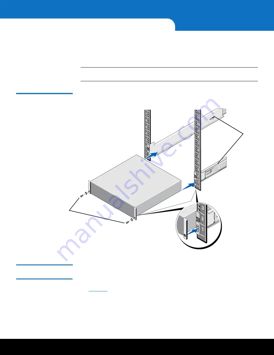
Install the end caps on either side of the module by inserting the top of the end cap 

first and then snapping the bottom into place.
Install the end cap with the indicator icons to the left of the module, and install the 

end cap with the drive numbers to the right of the module.

Note:

To remove the Array or Expansion module, remove the screws and slide the 

module out of the rack.

Figure 19  DXi6902 Array or 
Expansion Module Installation

Installing the DXi6902 

Node

Installing the DXi6902 Node Rack Mounting Rails

1

Position the left and right rail end pieces labeled 

FRONT

 facing inward, and orient 

each end piece to seat in the holes on the front side of the vertical rack flanges (see 

Figure 20

).

2

Align each back end piece in the bottom and top holes of the desired U spaces.

3

Engage the back end of the rail until it fully seats on the vertical rack flange and the 

latch clicks into place. Repeat these actions to position and seat the front end piece 

on the vertical rack flange.

Front of Array or 

Expansion module

10-32 x 3/4 in. screw 

and nylon washer

Rails

Summary of Contents for DXi6902

Page 1: ...SYSTEM IMPORTANT BEFORE YOU BEGIN 1 Read this entire document before your start to unpack or install the system 2 Make sure that you have all boxes that shipped with the system 3 Install and cable all...

Page 2: ......

Page 3: ...uirements 4 Environmental Conditions 4 Preparing for the Installation 5 Necessary Tools 5 Taking ESD Precautions 5 DXi6902 Installation Overview 6 Unpacking the DXi6902 7 Unpacking the DXi6902 Node 7...

Page 4: ...ports path to tape or ingest and read 2 x 10 GbE SFP Ethernet ports 3 x 1 GbE Ethernet ports Optional Additional network adapter providing 2 x 10 GbE SFP Ethernet ports or 4 x 1 GbE Ethernet ports 17...

Page 5: ...TB per module Storage capacity upgrades are enabled simply by adding a license key To purchase a storage capacity upgrade license contact your Quantum sales representative After you obtain the storage...

Page 6: ...equirements Table 2 contains the rack requirements for the DXi6902 components Table 2 DXi6902 Rack Requirements Environmental Conditions The installation site must have the following environmental con...

Page 7: ...orm initial system configuration Contact Quantum ASPS for the service password Taking ESD Precautions Some components within the DXi6902 system contain static sensitive parts To avoid damaging these p...

Page 8: ...g the DXi6902 on page 7 2 Optional Installing Components in the DXi6902 Node on page 12 a Opening the Node Cover on page 12 b Installing the Optional i350 or X520 Network Card on page 18 c Closing the...

Page 9: ...respectively A minimum of two people are required to lift either chassis Unpacking the DXi6902 Node The box containing the DXi6902 Node contains the following items Rack mount rails Cable management...

Page 10: ...Installation and Configuration Guide Carefully unpack and remove the components from the packing materials see Figure 2 Figure 2 Unpacking the DXi6902 Node DXi6902 Node Box Bezel key taped to back Rac...

Page 11: ...ork card One of the following network cable kits ships with the optional network card depending on configuration Cable kit quad 1GbE NIC Cable CAT6 RJ45 non plenum blue solid 25 feet 4 Cable kit dual...

Page 12: ...and Expansion Modules EBOD Do not mix Quantum Modules with NetApp Modules WARNING The DXi6902 Array Module RBOD and Expansion Module EBOD weigh 59 0 pounds 26 8 kg and 57 0 pounds 25 9 kg respectivel...

Page 13: ...Unpacking the DXi6902 11 DXi6902 Figure 4 Unpacking the DXi6902 Array Module or Expansion Module Foam DXi6902 Array Expansion module Box Rack mount rails End caps SAS and AC power cables...

Page 14: ...g the Memory Modules on page 15 Installing the Optional i350 or X520 Network Card on page 18 Closing the Node Cover on page 21 Opening the Node Cover To open the DXi6902 Node cover WARNING The DXi6902...

Page 15: ...6 Removing the Node Cover 5 Lift the latch on top of the Node and slide the cover back 6 Grasp the cover on both sides and carefully lift the cover away from the Node 7 Remove the cooling shroud by ho...

Page 16: ...on and Configuration Guide Figure 8 illustrates the interior of the DXi6902 Node with the cover removed Figure 8 Inside the DXi6902 Node 1 0 2 3 1 0 2 3 Cooling shroud Memory modules Expansion card ri...

Page 17: ...ode see Table 4 Memory modules must be installed in the correct sockets in order for the system to function properly see Figure 9 Note Memory socket numbers are displayed on the clear window on the co...

Page 18: ...allation and Configuration Guide Figure 9 Node Memory Module Locations White sockets 8 memory modules are pre installed at the factory for all configurations Black sockets Install 8 memory modules for...

Page 19: ...ocket see Figure 10 The plastic memory blanks are recyclable Figure 10 Installing a Memory Module 2 Align the memory module s edge connector with the alignment key of the memory module socket and inse...

Page 20: ...he chassis Installing the Optional i350 or X520 Network Card The following network card options are available for all DXi6902 configurations see Table 5 Dual port 10 GbE X520 card Provides two 10 GbE...

Page 21: ...rounding strap when performing this procedure 1 Holding the touch points lift the expansion card riser 1 from the riser connector on the system board see Figure 13 DXi6902 Configuration Actions to Tak...

Page 22: ...ansion card latch and rotate the latch away from the expansion card riser see Figure 14 Figure 14 Installing the Optional Network Card in Riser 1 3 Remove the metal slot cover from slot 2 by sliding i...

Page 23: ...em board see Figure 13 8 Optical 10 GbE option only Insert an SFP unit into each 10 GbE port on the X520 card The SFP units are included with the optional 10 GbE network card Closing the Node Cover To...

Page 24: ...6902 Determining the Order of the Components in the Rack To make it easier to correctly cable the system and for safety reasons follow these recommendations when installing the DXi6902 system in the r...

Page 25: ...ents from lowest in the rack to highest in the rack EBOD 2 6 EBOD 2 5 EBOD 2 4 EBOD 2 3 EBOD 2 2 EBOD 2 1 RBOD 2 DXi6902 Node EBOD 1 7 EBOD 1 6 EBOD 1 5 EBOD 1 4 EBOD 1 3 EBOD 1 2 EBOD 1 1 RBOD 1 2U b...

Page 26: ...ssis may cause the rack to become top heavy and unstable if installed in the top of an empty rack To mark the rack place a mark or tape on the rack s front vertical rails where you want to locate the...

Page 27: ...completely closed Quantum recommends that you do not remove the hard drives from the chassis If they have been removed for any reason during or after the installation you must install the hard drives...

Page 28: ...e 19 DXi6902 Array or Expansion Module Installation Installing the DXi6902 Node Installing the DXi6902 Node Rack Mounting Rails 1 Position the left and right rail end pieces labeled FRONT facing inwar...

Page 29: ...e proceeding ensure that all hard drive latches are completely closed Quantum recommends that you do not remove the hard drives from the chassis If they have been removed for any reason during or afte...

Page 30: ...ils and slide the system into the rack Note To remove the Node locate the lock levers on the sides of the inner rails Unlock each lever by rotating it up to its release position Grasp the sides of the...

Page 31: ...plugs can be plugged in upside down The cable will appear to be inserted but is not Verify the cable is seated by pulling lightly on the cable Verify the SAS link light is ON after powering on the RBO...

Page 32: ...Controller A on RBOD 1 to SAS port 1 Controller A on EBOD 1 1 b Connect SAS expansion port 1 Controller B on RBOD 1 to SAS port 1 Controller B on EBOD 1 1 c Connect SAS expansion port 1 Controller A o...

Page 33: ...port Controller A on the EBOD to SAS port 1 Controller A on the next EBOD in the sequence b Connect the SAS expansion port Controller B on the EBOD to SAS port 1 Controller B on the next EBOD in the s...

Page 34: ...D Diag Port 1 ID Diag Port 1 EBOD 1 7 EBOD 1 6 ID Diag Port 1 ID Diag Port 1 EBOD 1 4 EBOD 1 3 ID Diag Port 1 ID Diag Port 1 ID Diag Port 1 ID Diag Port 1 ID Diag Port 1 ID Diag Port 1 EBOD 1 5 EBOD 1...

Page 35: ...6 ID Diag Port 1 ID Diag Port 1 EBOD 2 6 EBOD 2 5 ID Diag Port 1 ID Diag Port 1 EBOD 2 3 EBOD 2 2 ID Diag Port 1 ID Diag Port 1 ID Diag Port 1 ID Diag Port 1 EBOD 2 4 EBOD 2 1 ID Diag Port 1 ID Diag...

Page 36: ...ect each Node power supply to a primary and secondary AC power source Use the attached straps to secure the power cords to the chassis Figure 26 DXi6902 Power Cabling 5 Do not connect any Ethernet cab...

Page 37: ...1 Power on the DXi6902 system components in the following order a Turn on both power switches on the back of each Expansion module EBOD see Figure 28 Wait until the seven segment display on the rear o...

Page 38: ...Service Port 3 Configure the network settings on the laptop Note This procedure assumes you are running Windows 7 on the laptop The steps might be different if you are using another operating system...

Page 39: ...IP address and then enter the following information Caution Before changing the IP address information write down the original settings This will be used later to reset the network configuration IP ad...

Page 40: ...in PTO Mode to continue with the installation as indicated by the text PTO Mode at the top of the Service Menu If the system is not in PTO Mode type the option for Enable PTO and press Enter Service...

Page 41: ...80e500034203f000000005329a075 Checking that controller A is online Checking that controller B is online Adjusting RBOD configurations Handling Qarray1 60080e500034203f000000005329a075 Starting autolev...

Page 42: ...oard Detecting ethernet Detecting bios Detecting cpu Detecting memory Detecting pci Detecting fc Detecting sas Detecting ipmi Detecting ipmi monitor Detecting nodes Probing for node 1 Found Detecting...

Page 43: ...The system displays information about attached Array Modules RBODs and Expansion Modules EBODS see Figure 38 Make sure all of the installed RBODs and EBODs are detected If one or more storage arrays...

Page 44: ...ll wipe and start a background RAID initialization for the external storage By default all attached storage trays will be wiped and used for the RAID initialization Do you want to continue y n 8 Type...

Page 45: ...Clearing out old configuration from Qarray1 Deleting the existing configuration Deleting all Volumes and Pools Set controller in duplex mode Setting the Storage Array user label to Qarray1 Set control...

Page 46: ...initialize and press Enter The system displays the following message This will start the Software initialization Do you want to continue y n 13 Type y and press Enter The system configures the StorNex...

Page 47: ...major steps See the following subsections for detailed instructions for completing each step 1 Completing the Getting Started Wizard 2 Connecting the Ethernet Cables 3 Installing the Capacity License...

Page 48: ...Login Window 2 On the Login window select Administrator type password for the password and click Login The Welcome page displays see Figure 42 Note If a message on the page indicates the DXi is in Li...

Page 49: ...e License Agreement page displays see Figure 43 Figure 43 Getting Started Wizard License Agreement 4 Select the I have read and accept this License Agreement check box and then click Next to continue...

Page 50: ...etwork settings on the DXi6902 In this example the DXi6902 is configured as follows All Ethernet ports are configured as individual devices Not Bonded A single network interface with one IP address is...

Page 51: ...Performing Initial Configuration 49 DXi6902 Figure 44 Getting Started Wizard Network...

Page 52: ...rs A Z numbers 0 9 dots and hyphens d Optional In the Primary Secondary and Tertiary DNS IP Address boxes enter the IP address of up to three DNS servers used to resolve domain names and translate the...

Page 53: ...teway The gateway of the DXi6902 This is usually not the same as the default gateway c Select the Any check box to allow all traffic types management replication and data on the interface d Click Upda...

Page 54: ...ze the system time with an NTP time server To select a timeserver pool you must have specified at least one DNS IP address in step 5d above Otherwise you must specify the IP address of the timeserver...

Page 55: ...e changes 16 After you have confirmed all settings click Finish A message appears stating that completing the setup will restart the system 17 Click Yes to restart the system 18 Disconnect the compute...

Page 56: ...to two 10 GbE optical cables Note Quantum DXi6902 systems support 10 GbE optical cable lengths of up to 300 meters with OM3 cables and up to 100 meters with OM2 cables Quantum recommends using the DXi...

Page 57: ...Optional 4 x 1 GbE Ports Figure 49 DXi6902 Ethernet Cabling Optional 2 x 10 GbE Ports 4 Install the protective bezel on the front of the DXi6902 Node The bezel snaps into place on the front of the Nod...

Page 58: ...ge Capacity License Certificate that was included with the system and then complete the following procedure 1 Open two Web browser windows on a computer with Internet access Note During this procedure...

Page 59: ...nfiguration 57 DXi6902 Figure 51 License Keys Page b In the other browser enter the address for the License Key Management Web site see Figure 52 http www quantum com licensekeys Figure 52 License Key...

Page 60: ...console see Figure 51 4 Enter the license key in the New Key box and click Add The file system is automatically expanded This can take up to 10 minutes 5 Click the Storage Capacity license link on th...

Page 61: ...r Configuration reports Using the Configuration Wizards Use the Configuration Wizards on the Wizards menu to configure the DXi for backups and to configure additional features VTL Wizard VTL configura...

Page 62: ...DXi refer to your backup application documentation To learn more about operating the DXi6902 refer to the Quantum DXi6902 User s Guide 6 68159 Or access the online help from the remote management con...

Page 63: ...ower switches on the back of each Array and Expansion module 3 Make sure all hard drives are inserted completely and all hard drive latches are closed 4 Make sure all memory modules are fully inserted...

Page 64: ...ries All other trademarks are the property of their respective owners Protected by Pending and Issued U S and Foreign Patents including U S Patent No 5 990 810 6 68160 01 B 62 6 68160 02 Rev A October...

Reviews: