
Installing the Desktop Tape Drive
DDS-4 / DAT 72
1. Unpack the contents of your drive package. If any item is damaged,
please contact your place of purchase immediately.
2. In addition to the contents included with your desktop tape drive, you
need the following items:
• A SCSI host bus adapter that is properly installed and configured
in a host computer
• A 50-to-68 pin adapter, if your computer has a narrow SCSI
interface connector.
• Backup application software that supports the tape drive. For a list of
the latest backup software applications tested with the DDS-4 and
DAT 72 tape drives, please visit our Web site at
www.Quantum.com/support.
3. Review the drive's default settings and change them if necessary:
(For detailed setting information and the location of switches, please
refer to your User's Guide on the Resource CD.)
• SCSI ID: 6
• Parity Checking: Enabled
• Terminator Power: Supplied to the SCSI bus
• Data Compression: Enabled
• Media Recognition (DDS-4 drives only): Enabled
• Power-On Self-Test: Enabled
• Host Operating System: Windows 98/Me/XP/NT/2000/2003 Server
• SCSI Interface Compatibility (DDS-4 drives only): Wide SCSI
• Vendor ID: SEAGATE DAT
4. Connect a SCSI interface cable to the drive. You can use either connector to
attach the drive to the host computer or to another SCSI device.
5. Check the SCSI termination.
6. Connect a power cable to the AC power connector on the back of the
tape drive. Connect the other end of the power cable to a working AC
outlet.
7. Turn on the computer, turn on the tape drive, and verify that the tape
drive is operating properly.
8. Register your tape drive at www.Quantum.com/registration.
Congratulations
You have purchased the finest, most reliable digital data storage (DDS) drive available. The DDS-4 and DAT
72 DDS drives represent Quantum’s commitment to engineering reliable and durable tape drive products that implement
leading-edge technology.
Designed for computer environments that require high-performance, high-capacity data storage, the DDS-4 and DAT 72
drives are based on a 3.5-inch mechanism and are available as internal, desktop, and rackmount tape drives. The drives
combine established Digital Audio Tape (DAT) technology, high-density recording, and hardware data-compression
capabilities with Quantum’s proven computer-grade design
to provide unmatched reliability and performance characteristics among DDS products.
1. Unpack the contents of your drive package. If any item is damaged, please contact
your place of purchase immediately.
2. In addition to the contents included with your internal tape drive, you need the
following items:
•
A SCSI host bus adapter that is properly installed and configured in a host
computer
•
A 3.5-inch or 5.25-inch half-height bay
•
A SCSI ribbon cable
•
Backup application software that supports the internal tape drive. For a list of
the latest backup software applications tested with the internal DDS-4 and
DAT 72 tape drives, please visit our Web site at www.Quantum.com/support.
3. Before proceeding with the installation, gather the tools you will need to install the
internal tape drive into the computer mounting bay. The following list identifies
some of the tools you will need. You may need additional items, depending on your
installation requirements.
•
Phillips screwdriver
•
Flatblade screwdriver, if your computer uses flathead screws
•
TORX screwdriver, if your computer uses TORX screws
•
Computer documentation, which you can refer to during the installation
4. Review the drive's default settings and change them if necessary:
(For detailed setting information, please refer to your User's Guide on the Resource
CD.)
•
SCSI ID: 6
•
Parity Checking: Enabled
•
Terminator Power: Supplied to the SCSI bus
•
Data Compression: Enabled
•
Media Recognition (DDS-4 drives only): Enabled
•
Power-On Self-Test: Enabled
•
Host Operating System: Windows 98/Me/XP/NT/2000/2003 Server
•
SCSI Interface Compatibility (DDS-4 drives only): Wide SCSI
•
Vendor ID: SEAGATE DAT
5. Turn off your computer, remove its covers and power cord, and select a mounting
bay for the drive. Depending on your drive, select a 3.5-inch or 5.25-inch bay.
6. Mount the drive into the bay and secure using the supplied screws.
7. Connect a SCSI interface cable to the drive. The internal tape drives can be used with two
SCSI interfaces:
•
Wide SCSI — either Low Voltage Differential (LVD) or Single-ended (16-bit
Wide mode),
•
Narrow SCSI — either Low Voltage Differential (LVD) or Single-ended (8-bit
Wide mode).
The tape drive automatically detects whether the SCSI bus is LVD or single ended. Be
sure the SCSI bus is terminated properly.
8. Be sure the internal tape drive is not the last device on the SCSI bus (the drive does
not provide SCSI termination).
9. Connect a spare 4-pin power cable from the computer ’s internal power supply to
the power connector on the back of the internal tape drive.
10. Replace the computer covers and power cord, turn on the computer, and verify that
the internal tape drive is operating properly.
11. Register your tape drive at www.Quantum.com/registration.
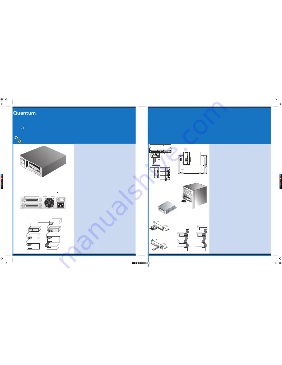
External Drive
Internal Tape Drive
Jumper Settings
Internal Tape Drive Switch Settings
Internal Drive
Mounting an Internal Tape Drive
SCSI Interface Connector
Power Connector
Back Panel of the External Tape Drive
SCSI Termination Examples of the External Tape Drive
SCSI Termination Examples for the Internal Tape Drive
Copyright © 2005 by Quantum Corporation. All Rights Reserved.
Quantum and the Quantum logo are trademarks of Quantum LLC. Other product names are trademarks or registered trademarks of their respective owners. Quantum reserves the right to
change, without notice, product offerings or specifications. No part of this publication may be reproduced in any form without written permission from Quantum LLC.
• Part number 10011125-101
May 2005
Installing the Internal Tape Drive
DDS-4 / DAT 72
Important Safety Precautions
Your internal tape drive has very sensitive components that are prone to damage from electrostatic discharge (ESD). Use extreme care when handling the drive, as it
can be damaged by ESD. Before handling the drive, read these ESD instructions to prevent damage to the drive.
• Wear an ESD-preventive grounding wrist strap or observe similar ESD precautions when working with the drive. Be sure the wrist strap makes good skin contact. Do
not remove the wrist strap until you finish working with the drive.
• Avoid contact between the drive, other equipment, and clothing. The wrist strap only protects the equipment from ESD voltages on the body; ESD voltages on
clothing can still cause damage.
• When the drive is not being used, keep it in its antistatic bag.
• Before you remove the drive from the antistatic bag, touch a metal or grounded surface to discharge any static electricity buildup from your body.
• Hold the drive by its edges only. Avoid touching any exposed parts on the printed circuit board.
• Always place the drive on top of or inside the antistatic bag to reduce the chance of ESD damage.
NOTE: If you have a desktop drive, refer to the other side of this card for installation instructions.
External
Tape Drive
SCSI Controller
(termination enabled)
External
SCSI device
External
Tape Drive
SCSI Terminators
SCSI Controller
(termination disabled)
Internal SCSI device
(
termination enabled
)
Example 1:
SCSI termination in a system
that has only external SCSI devices.
External
SCSI device
SCSI ID selector
68-pin wide SCSI
connectors
Example 2:
SCSI termination in a system that
has both internal and external SCSI devices.
Data compression (DC)
SCSI DC control
Media recognition
Self Test
Wide/Narrow SCSI
Inquiry String support
1
2
3
4
5
6
7
8
9
10
O
N
Default settings shown
Front of drive
Operating-system
configuration
switches
SCSI ID=0
SCSI ID=1
SCSI ID=2
SCSI ID=3
SCSI ID=4
SCSI ID=5
SCSI ID=6
SCSI ID=7
SCSI ID=8
SCSI ID=9
SCSI ID=10
SCSI ID=11
SCSI ID=12
SCSI ID=13
SCSI ID=14
SCSI ID=15
Parity enable
Term. power
Default jumper settings shown
(SCSI ID 6, parity checking enabled,
and termination power disabled)
Pins:
Function:
1-2
SCSI ID bit 0
3-4
SCSI ID bit 1
5-6
SCSI ID bit 2
7-8
SCSI ID bit 3
9-10
Parity checking
11-12
Termination Power
SCSI Controller
(termination enabled)
Tape drive
SCSI device
SCSI device
(
termination
enabled
)
(
termination
disabled
)
(no
termination
)
SCSI Terminator
SCSI Controller
(termination enabled)
Tape drive
(no
termination
)
C
M
Y
CM
MY
CY
CMY
K
10011125-101.pdf 9/28/2005 12:09:21 PM
10011125-101.pdf 9/28/2005 12:09:21 PM


