background image

Chapter 2 

23 

QDSP-2060 User’s Manual 


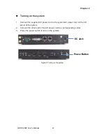
Turning on the system


1.  Connect the supplied AC power cord to the system AC power inlet on the I/O 

panel of the system.   

2.  Connect the other end of the AC power cord to a corresponding outlet. 

3. 

Press the power switch to turn on the system


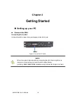
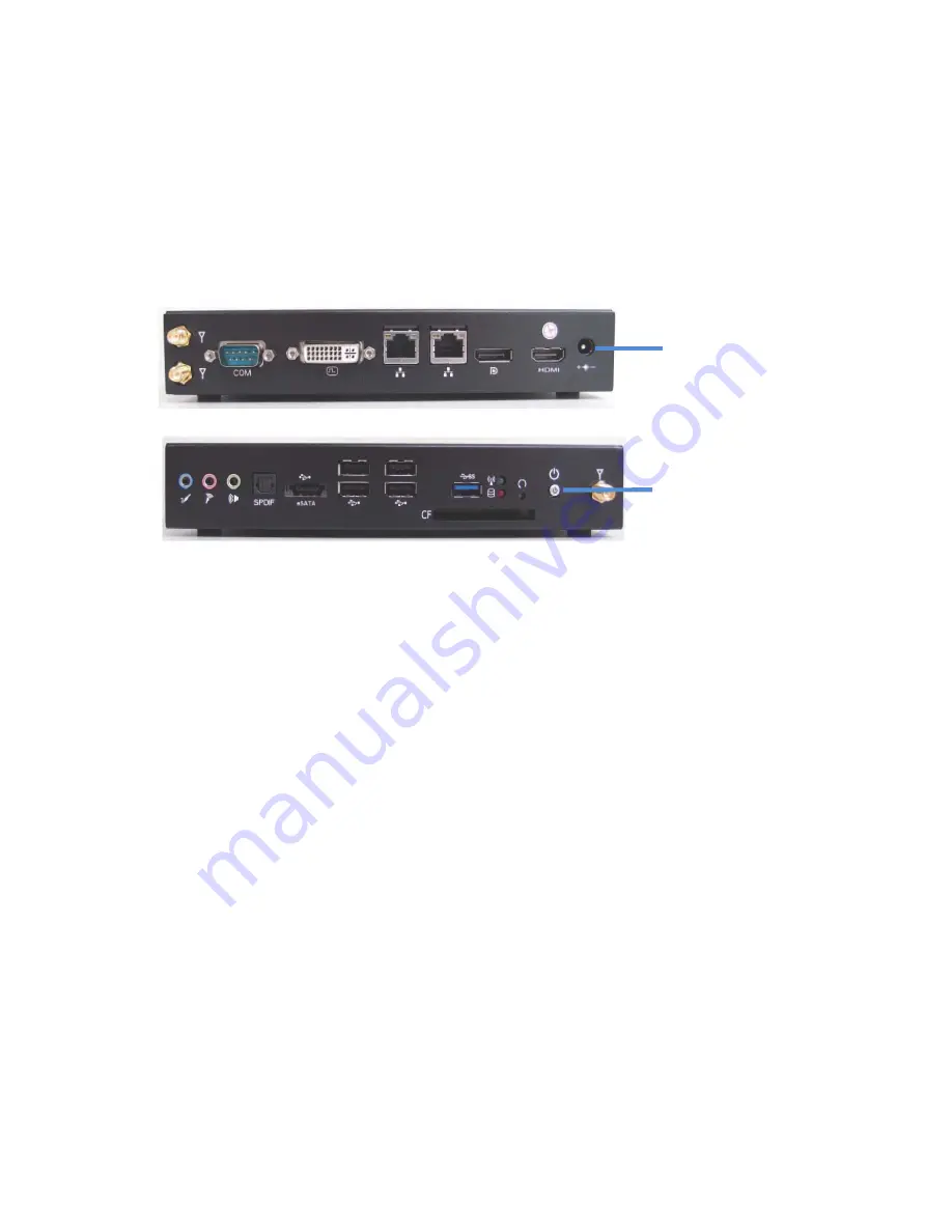
Figure 8 Turning on the system 


Power Button 

DC Jack 

Summary of Contents for QDSP-2060

Page 1: ...I QDSP 2060 User s Manual QDSP 2060 Small PC with 2nd Generation Intel Core i3 i5 i7 Processors User s Guide...

Page 2: ...s of others Quanmax is a registered trademark of Quanmax All trademarks registered trademarks and trade names used in this user s guide are the property of their respective owners All rights reserved...

Page 3: ...ory Compliance Statements 9 Warranty Policy 10 Maintaining Your Computer 11 Chapter 1 Introduction 14 Overview 14 Product Specifications 15 System tour 16 Mechanical Dimensions 19 Chapter 2 Getting St...

Page 4: ...Installation 2 27 Figure 16 Mini PCIe Installation 28 Table 1 QDSP 2060 product specifications 15 Table 2 BIOS Main Menu 30 Table 3 Advanced Menu 31 Table 4 Advanced Menu Display Configuration 32 Tabl...

Page 5: ...Figures Tables 5 QDSP 2060 User s Manual Table 17 Save Exit Menu 43...

Page 6: ...extreme caution when installing or removing components Refer to the installation instructions in this user s guide for precautions and procedures If you have any questions please contact Quanmax Post...

Page 7: ...onnector or on its strain relief loop not on the cable itself Some cables have a connector with locking tabs If you are disconnecting this type of cable press in on the locking tabs before disconnecti...

Page 8: ...care Don t touch the components or contacts on a board Hold a board by its edges or by its metal mounting bracket Do not handle or store system boards near strong electrostatic electromagnetic magnet...

Page 9: ...amage If there is damage notify Quanmax customer service immediately Refer to Warranty Policy for the return procedure Regulatory Compliance Statements This section provides the FCC compliance stateme...

Page 10: ...d Warranty Quanmax Inc s detailed Limited Warranty policy can be found under Support at www quanmax com Please consult your distributor for warranty verification The limited warranty is void if the pr...

Page 11: ...in compliance with this Limited Warranty Return Policy will not be accepted by Quanmax Limitation of Liability In no event shall Quanmax be liable for any defect in hardware software loss or inadequac...

Page 12: ...re power loss power spikes and power surges caused by electrical storms which interrupt system operation and or damage system components To protect your system always properly ground power cables and...

Page 13: ...ding on the UPS system UPS systems range in price from a few hundred dollars to several thousand dollars with the more expensive unit s allowing you to run larger systems for a longer period of time w...

Page 14: ...hipset it provides the powerful computing and graphic performance with the optimal energy efficiency Checklist QDSP 2060 Power Adapter Power Cord Driver CD Quick installation Guide VESA Mounting Kit F...

Page 15: ...external antenna Rear IO 1x DC JACK for DC19V single power input 1x DVI I for DVI D or VGA output 1x HDMI 1x DP 2x RJ 45 GbE ports 1x COM Port support RS 232 422 485 Offer 5V selection 2x Wifi extern...

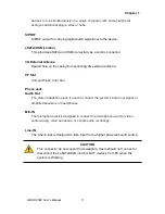
Page 16: ...MOS Button To clear the CMOS use the tip of a pen to press the button briefly for less than three seconds WiFi LED Green The WiFi LED will light when the WiFi is on Storage LED Red The hard disk card...

Page 17: ...3G external antenna CF Slot CompactFlash Card Slot Phone Jack Audio Out The stereo headphone jack is used to connect the system s audio out signal to amplified speakers or headphones MIC IN The micro...

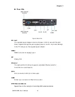
Page 18: ...To prevent damage to the PC always use the supplied power adapter HDMI HDMI connector for display output DP Display Port Ethernet The eight pin RJ 45 LAN port supports a standard Ethernet cable for co...

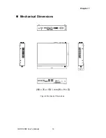
Page 19: ...Chapter 1 19 QDSP 2060 User s Manual Mechanical Dimensions 200 x 35 x 153 1 mm W x H x D Figure 3 Mechanical Dimensions...

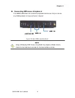
Page 20: ...ecting the monitor Connect the DVI I cable from your display to the DVI I port Figure 4 Connect the DVI cable NOTE When the system reboots without connecting the DVI there might be no image on screen...

Page 21: ...me with a keyboard and mouse but you can use any USB keyboard or mouse with your computer Figure 5 Connect USB mouse keyboard NOTE Using a third party USB mouse or keyboard may require software driver...

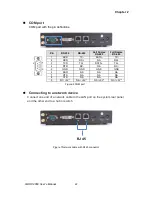
Page 22: ...TX 2 RXD RX NA RX 3 TXD TX DATA TX 4 DTR RX NA RX 5 GND GND GND GND 6 DSR NA NA NA 7 RTS NA NA NA 8 CTS NA NA NA 9 RI 5V NA 5V NA 5V NA 5V Figure 6 COM port Connecting to a network device Connect one...

Page 23: ...nnect the supplied AC power cord to the system AC power inlet on the I O panel of the system 2 Connect the other end of the AC power cord to a corresponding outlet 3 Press the power switch to turn on...

Page 24: ...e out the VESA mounting kit form your package and facing it onto the bottom of QDSP 2060 then tightening the screws on your QDSP 2060 as figures shown below Figure 9 VESA Mount Assembly 2 Following fi...

Page 25: ...ondly place the QDSP 2060 on the VESA mounting kit and then tightening the screws from the holes on both sides of the VESA bracket make sure the computer is fitting well on the bracket Figure 11 VESA...

Page 26: ...oosening the two screws on the bottom of QDSP 2060 as shown below Figure 12 Opening the Cover on the Bottom Then you may able to change the DDR SO DIMM and or mini PCIe modules Figure 13 Bottom view o...

Page 27: ...egree angle into the socket Figure 14 SO DIMM Installation 1 Align the SO DIMM Memory Module with the onboard socket 4 Fully insert the module into the socket until a click is heard 5 Press down on th...

Page 28: ...28 QDSP 2060 User s Manual Changing mini PCIe 1 Place your mini PCIe module toward the mini PCIe socket Figure 16 Mini PCIe Installation 2 Tightening the screw on the hole of the mini PCIe module as s...

Page 29: ...ase contact Quanmax AMI s ROM BIOS provides a built in Setup program which allows the user to modify the basic system configuration and hardware parameters The modified data will be stored in a batter...

Page 30: ...ate between menu screens Table 2 BIOS Main Menu BIOS SETUP UTILITY M a i n A d v a n c e d B o o t S e c u r i t y S a v e E x i t Product Information Select Screen Select Item Enter Select Change Opt...

Page 31: ...ontroller Enabled Onboard LAN2 Boot Disabled Audio Controller Enabled Display Configuration Super IO Configuration Power Management Configuration CPU Advanced Configuration Trusted Computing SATA Conf...

Page 32: ...Exit Primary Display IGFX Internal Graphics Enabled Aperture Size 256 MB DVMT Pre Allocated 64M DVMT Total Gfx Mem 256 M IGFX Boot Type VBIOS Default IGFX 2nd Boot Type Disabled Version 2 10 1208 Copy...

Page 33: ...g m t S a v e E x i t Serial Port 1 Configuration Select Screen Select Item Enter Select Change Opt F1 General Help F2 Previous Values F3 Optimized Defaults F4 Save Exit ESC Exit Serial Port Enabled...

Page 34: ...pend to RAM Restore AC Power Loss Power Off Resume By PCIE Device Disabled Resume By RTC Alarm Disabled EUP Power Saving Mode Disabled Watchdog Timer Configuration Version 2 10 1208 Copyright C 2010 A...

Page 35: ...F2 Previous Values F3 Optimized Defaults F4 Save Exit ESC Exit EIST Enabled Intel Virtualization Tech Disabled Active Processor Cores All Limit CPUID Maximum Disabled Execute Disable Bit Enabled Versi...

Page 36: ...C 2010 American Megatrends Inc TPM Options Disabled Enabled Table 10 Advanced Menu SATA Configuration BIOS SETUP UTILITY M a i n A d v a n c e d B o o t S e c u r i t y S a v e E x i t SATA Controller...

Page 37: ...n c e d B o o t S e c u r i t y S a v e E x i t Intel AMT Enabled Intel AMT Setup Prompt Enabled BIOS Hotkey Pressed Disabled MEBx Selection Screen Disabled Verbose MEBx Output Enabled Hide Un Config...

Page 38: ...utput Options Disabled Enabled Un Configure ME Options Disabled Enabled Intel AMT Password Write Enabled Options Disabled Enabled AMT Wait Timer Options 0 only ASF Options Disabled Enabled Activate Re...

Page 39: ...ice power up delay Auto Mass Storage Devices San Disk Auto Select Screen Select Item Enter Select Change Opt F1 General Help F2 Previous Values F3 Optimized Defaults F4 Save Exit ESC Exit Version 2 10...

Page 40: ...t ESC Exit CPU Smart FAN Temperature 1 70 CPU Smart FAN Temperature 2 90 CPU Smart FAN PWM 1 50 CPU Smart FAN PWM 1 150 CPU Manual PWM 255 CPU Temperature 90 C Top Side System Temperature 31 C Bottom...

Page 41: ...Display Disabled Setup Prompt Timeout 1 Bootup NumLock State On Boot Option Priorities Boot Option 1 SanDisk Boot Option 2 UEFI USB USB Hard Hard Drive BBS Priorities Version 2 10 1208 Copyright C 201...

Page 42: ...only asked for when entering Setup If ONLY the User s password is set then this is a power on password and must be entered to boot or enter Setup In Setup the User will have Administrator rights The...

Page 43: ...and Exit Save Changes and Reset Discard Changes and Reset Save Options Save Changes Discard Changes Restore Defaults Save as User Defaults Restore User Defaults Boot Override San Disk UEFI USB USB Ha...

Page 44: ...OS asks for a confirmation before exiting Discard Changes Discards changes done so far to any of the setup values This option allows you to discard the selections you made and restore the previously s...

Page 45: ...m and the necessary drivers to operate it After you have finished assembling your system and connected the appropriate power source power it up using the power supply and install the desired operating...

Reviews: