background image

37

English

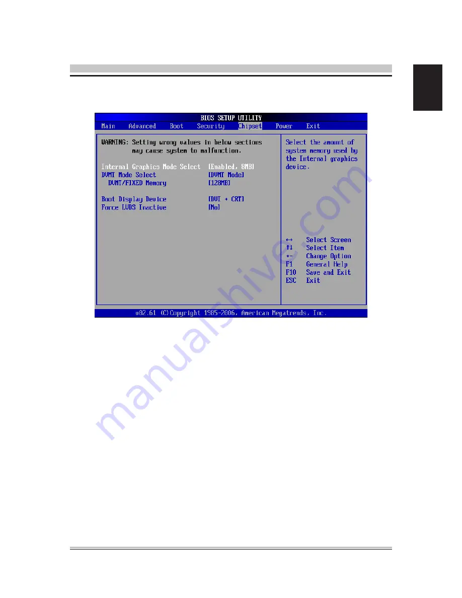
 3.6 Chipset


»

Internal Graphics Mode Select

The field specifies the size of system memory allocated for video memory.


»

DVMT Mode Select

Intel's Dynamic Video Memory Technology (DVMT) allows the system to dynamically allo-

cate memory resources according to the demands of the system at any point in time. The 

key idea in DVMT is to improve the efficiency of the memory allocated to either system 

or graphics processor.


»

Boot Display Device

Use the field to select the type of device you want to use as the display(s) of the system.


»

Force LVDS Inactive

This setting determines whether to force the LVDS inactive or not.

DVMT/FIXED Memory

When set to DVMT/FIXED Mode, the graphics driver will allocate a fixed amount of 

memory as dedicated graphics memory, as well as allow more system memory to 

be dynamically allocated between the graphics processor and the operating system.

Summary of Contents for QBOX-2020

Page 1: ...QBOX 2020 Fanless Box Computing User s Manual Version 1 0...

Page 2: ...or use of this product Quanmax Inc makes no representation or warranty regarding the content of this manual Information in this manual had been carefully checked for accuracy however no guar antee is...

Page 3: ...r extension cord These devices could interrupt the grounding circuit Make sure that your power supply is set to the correct voltage in your area If you are not sure about the voltage of the electrical...

Page 4: ...2 1 System Introduction 20 2 2 Opening Chassis 21 2 3 Installing Memory 22 2 4 Installing HDD 23 2 5 Installing SSD 24 2 6 Installing MINI PCI Express Expansion Card WiFi Module 25 2 7 Installing CF C...

Page 5: ...hipset 2 x Intel 82574L Gigabit Ethernet Watchdog 1 255 level reset Serial Port Support 2 x RS 232 ports and 1 x RS232 422 485 USB Port 4 x USB 2 0 ports LAN 2 x RJ45 ports for GbE Video Port 1 x DVI...

Page 6: ...14 5 Procedure 1 Category 4 Shock Crash Operating 20G 11ms Non Operating 60G with HDD Operating 40G 11ms Non Operating 80G with SSD Crash 100G 11ms Power Input DC 12V Input Construction Aluminum alloy...

Page 7: ...7 English System 182 195 64 209 64 60 120 167 6 34 95 41 6...

Page 8: ...the DIMM1 SO DIMM slot Align the notch on the DIMM with the key on the slot and insert the DIMM into the slot at 45 degree angle 2 Push the DIMM gently forwards until the slot levers click and lock th...

Page 9: ...Connector JPWR1 This connector provides power to the hard disk drives 12V System Power Connector PWR1 This connector provides power to the hard disk drives Important Power supply of 200watts and above...

Page 10: ...1 5 RJ 45 LAN Connector LEDs Speed Indicator Activity Indicator Left LED Right LED Active LED 100M 1000 Speed LED LED Color Yellow Green Orange 10M Cable Plug in No Transmission OFF OFF Transition Yel...

Page 11: ...nnected to your monitor refer to your monitor manual for more information Serial Port The serial port is a 16550A high speed communications port that sends receives 16 bytes FIFOs You can attach a ser...

Page 12: ...e Connector JKBMS1 This connector is used to connector PS 2 keyboard mouse PIN SIGNAL PIN SINNAL 1 3 5 7 9 VCC3_SB SPI_MISO_F SPI_CS0_F GND SPI_HOLD 2 4 6 8 10 VCC3_SB SPI_MOSI_F SPI_CLK_F GND NC PIN...

Page 13: ...4 15 16 17 18 19 20 COM_NDCD2 COM_NRD2 COM_NTD2 COM_NDTR2 GND COM_NDSR2 COM_NRTS2 COM_NCTS2 VCC_COM2 No Connection COM_NDCD3 COM_NRD3 COM_NTD3 COM_NDTR3 GND COM_NDSR3 COM_NRTS3 COM_NCTS3 VCC_COM3 No C...

Page 14: ...esign Guide PIN SIGNAL PIN SINNAL 1 3 5 7 9 GND N_GPO 3 N_GPO 2 N_GPI 3 N_GPI 2 2 4 6 8 10 VCC5 N_GPO1 N_GPO 0 N_GPI 1 N_HPI 0 PIN SIGNAL DESCRIPTION 1 2 3 4 5 6 7 8 9 10 HD_LED FP PWR SLP HD_LED FP P...

Page 15: ...NEout_JD Microphone Left channel Ground Microphone Right channel Active low signal signals BIOS that a High Definition Audio dongle is connected to the analog header PRESENCE 0 when a High Definition...

Page 16: ...JVDD1 jumper p 18 to proper power voltage SIGNAL PIN SIGNAL 12V 12V GND GND LCD_VDD LDDC_DATA LVDS_VDDEM GND LA_DATA0 LA_DATA1 LA_DATA2 LA_CLK LA_DATA3 GND LB_DATA0 LB_DATA1 LB_DATA2 LB_CLK LB_DATA3...

Page 17: ...nnect ing high speed USB interface peripherals such as USB HDD digital cameras MP3 play ers modems and the like PIN SIGNAL PIN SINNAL 1 3 5 7 USB_RSTR SBD1 SBD1 GND 2 4 6 8 GND SBD0 SBD0 USB_RSTR USB...

Page 18: ...om an external battery to keep the data of system configuration With the CMOS RAM the system can automati cally boot OS every time it is turned on If you want to clear the system configuration set the...

Page 19: ...nnect Express Slot The PCI Express slot supports the PCI Express interface expansion card The CON1 is a Mini PCI E connector for wireless LAN TV tuner and Robson NAND Flash Important When adding or re...

Page 20: ...English 2 1 System Introduction USB2 0 Port USB2 0 Port DC 12V Input COM2 Port COM1 Port External Antenna LAN Port DVI COM3 GPIO Power LED Mic In Power Button HDD SSD LED Line Out 2 System Installati...

Page 21: ...21 English 2 2 Opening Chassis Step 1 Unscrew the four screws of the Back Cover and the two screws of theFront Panel as shown in the picture Step 2 Open the Back Cover as shown in the picture...

Page 22: ...gned with the Memory socket of the board and insert it at a 30 degree angle into the socket as shown in the picture Step 3 Fully insert the module into the socket until a click is heard as shown in th...

Page 23: ...Put the HDD on the Back Cover as shown in the picture Step 2 Turn over the Back Cover and screw the four screws of the Back Cover as shown in the picture Step 3 Connect the HDD power cable and SATA c...

Page 24: ...1 Put the SSD on the bracket as shown in the picture Step 2 Screw the one screw of the SSD holder as shown in the picture Step 3 Connect the SSD power cable and SATA cable to SSD as shown in the pict...

Page 25: ...nsion Card on this place as shown in the picture Step 2 Hold the Module with its notch aligned with the socket of the board and insert it at a 30 degree angle into the socket as shown in the picture S...

Page 26: ...rews of the Back Cover as shown in the picture Step 2 Open the Back Cover as shown in the picture Step 3 Take the CF Card and Insert it into the socket as shown in the picture Step 4 Make sure the CF...

Page 27: ...n this chapter are under continuous update for better system performance Therefore the description may be slightly dif ferent from the latest BIOS and should be held for reference only Upon boot up th...

Page 28: ...unctions you can make changes to You can use the arrow keys to select the item The on line description of the highlighted setup func tion is displayed at the bottom of the screen Sub Menu If you find...

Page 29: ...type manually LBA Large Mode Enabling LBA causes Logical Block Addressing to be used in place of Cylinders Heads and Sectors Block Multi Sector Transfer Any selection except Disabled determines the n...

Page 30: ...30 English 3 3 Advanced CPU Configuration...

Page 31: ...code can execute and where it cannot When a malicious worm attempts to insert code in the buffer the processor disables code execution preventing damage or worm propagation Hyper Threading Technology...

Page 32: ...SB controller USB 2 0 Controller This setting enables disables the onboard USB controller Audio Controller This setting enables disable the onboard USB controller LAN Option ROM The items enable or di...

Page 33: ...cify the operation mode of the specified serial prots Watch Dog You can enable the system watch dog timer a heardware timer that generates either an NMI or a reset when the software that it monitors d...

Page 34: ...ration GPIO Configuration These items display the current status of all monitored hardware devices components such as voltages temperatures and all fans speeds GP 60 61 62 63 64 65 66 67 Data These se...

Page 35: ...ts to load the disk operating system Try Other Boot Devices Setting the option to Enabled allows the system to try to boot from other device if the system fail to boot from the 1st 2nd 3rd boot device...

Page 36: ...d User Password controls access to the system at boot These settings allow you to set or change the user password Boot Sector Virus Protection This function protects the BIOS from accidental corruptio...

Page 37: ...improve the efficiency of the memory allocated to either system or graphics processor Boot Display Device Use the field to select the type of device you want to use as the display s of the system Forc...

Page 38: ...tion If your operating system supports ACPI you can choose to enter the Standby mode in S1 POS or S3 STR fashion through the setting of this field Restore on AC Power Loss This setting specifies wheth...

Page 39: ...ill be awadened from power saving modes when activity or input signal of onboard LAN is detected Resume On PME When setting to Enabled the feature allows your system to be awakended from the power sav...

Page 40: ...up Utility Discard Changes Abandon all changes and continue with the Setup Utility Load Optimal Defaults Use this menu to load the default values set by the mainboard manufacturer specifically for opt...

Page 41: ...mov al 87h out dx al mov al 01h out dx al mov al 55h out dx al out dx al 2 Set to LDN 07 mov dx SIO_IDX mov al 07h out dx al mov dx SIO_DTA mov al 07h out dx al 3 Set WatchDog Timer mov dx SIO_IDX mov...

Page 42: ...pset initialization Re enable CACHE Verify that flat mode is enabled D4 Test base 512KB memory Adjust policies and cache first 8MB Set stack D5 Bootblock code is copied from ROM to lower system memory...

Page 43: ...st to CH 2 count reg Initialize CH 0 as system timer Install the POSTINT1Ch handler Enable IRQ 0 in PIC for system timer interrupt Traps INT1Ch vector to POSTINT1ChHandlerBlock 08 Initializes the CPU...

Page 44: ...n 38 Initializes different devices through DIM See DIM Code Checkpoints section of document for more information 39 Initializes DMAC 1 DMAC 2 3A Initialize RTC date time 3B Test for total memory insta...

Page 45: ...ules Fill the free area in F000h segment with 0FFh Initializes the Microsoft IRQ Routing Table Prepares the runtime lan guage module Disables the system configuration display if needed A4 Initialize r...

Page 46: ...RT 3VSB SMBALERT F19 GPIO12 I O Unmultiplexed 3VSB SPI_HOLD_GPO E19 GPIO13 I O Unmultiplexed 3VSB SIO_PME R4 GPIO14 I O Unmultiplexed 3VSB VOLUME E22 GPIO15 I O Unmultiplexed 3VSB 3VSB AC22 GPIO16 I O...

Page 47: ...CLKRUN AC19 GPIO33 I O AZ_DOCK_EN VCC3 PRES2 U2 GPIO34 I O AZ_DOCK_RST VCC3 PRES3 AD21 GPIO35 I O SATACLKREQ VCC3 PRES1 AH19 GPIO36 I O SATA2GP VCC3 SATA2GP AE19 GPIO37 I O SATA3GP VCC3 SATA3GP AD20 G...

Page 48: ...GB DDRII SO DIMM Memory Optional 5 2 GB DDRII SO DIMM Memory Optional 6 2 5 160GB Hard Disk Drive Optional 7 802 11 b g n WiFi Kit Optional 8 8GB MLC Type SSD Optional 9 16GB MLC Type SSD Optional 10...

Reviews: