background image

Hard Drive Installation        2-5

KPC-1006RT User’s Guide

X

Hard Drive Installation

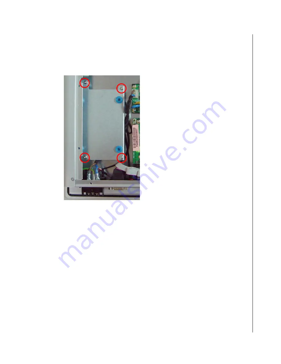
The KPC-1006RT comes with an Anti-vibration Hard Drive Mount for 2.5” hard drives. The mount is pre-

installed in the chassis as shown in 

Figure 2-2

 above. Loosen the four screws with a Phillips screwdriver as 

shown below and remove the bracket from the chassis.

KPC-1006RT

Figure 2-3. Remove the Anti-vibration HDD Bracket from the chassis

Summary of Contents for KPC-1006RT

Page 1: ...KPC 1006RT Industrial Panel PC User s Guide Rev 2 00 May 1 2008...

Page 2: ...emarks and trade names used in this user s guide are the property of their respective owners All rights reserved This user s guide contains information proprietary to Quanmax Customers may reprint and...

Page 3: ...ing Your Computer xx Environmental Factors xx Power Protection xxi Chapter 1 Product Introduction Overview 1 3 Checklist 1 4 Features 1 5 Product Specifications 1 6 Mechanical Layout 1 7 I O Panel 1 7...

Page 4: ...ii KPC 1006RT User s Guide Chapter 4 Maintenance Maintenance and Prevention 4 3 Chapter 5 Interfaces External Connectors 5 3...

Page 5: ...1 COM4 RS 232 Serial Port Connector pin definition 5 3 Table 5 2 COM2 RS232 422 485 Serial Port Connector pin definition 5 3 Table 5 3 COM2 RS232 422 485 Mode Select jumper settings 5 3 Table 5 4 VGA...

Page 6: ...iv KPC 1006RT User s Guide...

Page 7: ...i Vibration Bracket 2 6 Figure 2 5 Replace the Anti Vibration Bracket with HDD into the chassis and connect the IDE cable 2 7 Figure 2 6 Panel mounting the KPC 1006RT 2 8 Figure 2 7 Secure the chassis...

Page 8: ...vi KPC 1006RT User s Guide...

Page 9: ...X Safety Instructions Contents Before You Begin ix When Working Inside a Computer x Preventing Electrostatic Discharge xi Instructions for Lithium Battery xii Voltage Ratings xii...

Page 10: ...viii KPC 1006RT User s Guide This page intentionally left blank...

Page 11: ...tronics service personnel should access the interior of a computer The power supplies produce high voltages and energy hazards which can cause bodily harm Use extreme caution when installing or removi...

Page 12: ...id possible damage to system boards wait five seconds after turning off the computer before removing a component removing a system board or disconnecting a peripheral device from the computer When you...

Page 13: ...emove the component s antistatic packing material until you are ready to install the component in a computer Just before unwrapping the antistatic packaging be sure you are at an ESD workstation or gr...

Page 14: ...Only replace with the same or equivalent type recommended by the manufacturer Do not dispose of lithium batteries in domestic waste Dispose of the battery according to the local regulations dealing w...

Page 15: ...acking xvi Regulatory Compliance Statements xvii Warranty Policy xviii Limited Warranty xviii Return Procedure xviii Limitation of Liability xviii Maintaining Your Computer xix Cleaning Components xix...

Page 16: ...xiv KPC 1006RT User s Guide This page intentionally left blank...

Page 17: ...stem architecture for the KPC 1006RT Chapter 2 Assembly Disassembly describes how to access the system s internal components and locations of connectors so that you can easily configure your system Ch...

Page 18: ...ing material for possible future shipment 2 Remove all items from the box If any items listed on the purchase order are missing notify Quanmax customer service immediately 3 Inspect the product for da...

Page 19: ...uses and can radiate radio frequency energy and if not installed and used in accordance with the user s guide may cause harmful interference to radio communications Operation of this equipment in a r...

Page 20: ...redit must be accompanied by a Return Material Authorization RMA Number Freight on all returned items must be prepaid by the customer who is responsible for any loss or damage caused by common carrier...

Page 21: ...se moisture to enter and accumulate in the system This moisture can cause corrosion of internal components and degrade such properties as electrical resistance and thermal conductivity Extreme moistur...

Page 22: ...y constant level and therefore can handle brownouts Because of this added protection line conditioners cost more than surge protectors However line conditioners cannot protect against a complete loss...

Page 23: ...Chapter 1 X Product Introduction Contents Overview 1 3 Checklist 1 4 Features 1 5 Product Specifications 1 6 Mechanical Layout 1 7 I O Panel 1 7 Mechanical Dimensions 1 8...

Page 24: ...1 2 KPC 1006RT User s Guide This page intentionally left blank...

Page 25: ...ronments and is equipped with an Intel Celeron M processor at 600MHz with 512 KB L2 cache 2 5 HDD bay with anti vibration mount CompactFlash LAN USB 2 0 COM and VGA out To meet current trends towards...

Page 26: ...ton box check if the unit is properly secure in the plastic bag 2 Check the contents of the carton box Panel PC Driver CD Panel Mount Kit 5 brackets 5 screws If any of these items is damaged or missin...

Page 27: ...M GMCH and Intel I O Controller Hub 4 ICH4 chipset 1x SO DIMM slot up to 1GB X Input Output The KPC 1006RT has the following I O interfaces 1x Fast Ethernet 3x Serial Port COM2 supports RS 232 422 485...

Page 28: ...D with antivibration mount 1x CompactFlash Type II socket I O 1x Fast Ethernet COM 2x RS 232 1x RS 232 422 485 2x USB 2 0 Line out PS 2 Keyboard Mouse VGA out Expansion Mini PCI slot Power Supply DC 1...

Page 29: ...Mechanical Layout 1 7 KPC 1006RT User s Guide X Mechanical Layout X I O Panel KPC 1006RT DC in LAN COM4 PWR KB MS COM2 COM1 USB VGA Line Out Figure 1 1 KPC 1006RT Mechanical Layout I O Panel...

Page 30: ...1 8 KPC 1006RT User s Guide X Mechanical Dimensions Figure 1 2 KPC 1006RT Mechanical Dimensions...

Page 31: ...Chapter 2 X Assembly Disassembly Contents Accessing Internal Components 2 3 Hard Drive Installation 2 5 Panel Mounting 2 8 VESA Wall Mounting 2 10...

Page 32: ...2 2 KPC 1006RT User s Guide This page intentionally left blank...

Page 33: ...s to prevent electric shock or system damage Follow the procedure described below to access the system s internal components 1 Place the system front side down on a soft material to prevent marking or...

Page 34: ...de it to one side to break the adhesion of the thermal pads on the CPU and Northbridge head spreaders Note the locations of the internal components of the system Hard Drive Mount Mini PCI slot Heat Sp...

Page 35: ...Anti vibration Hard Drive Mount for 2 5 hard drives The mount is pre installed in the chassis as shown in Figure 2 2 above Loosen the four screws with a Phillips screwdriver as shown below and remove...

Page 36: ...he screw pack to mount the 2 5 hard drive onto the blue vibration dampers on the Anti Vibration Bracket as shown Place the 2 5 HDD onto the vibration dampers as shown Flip the HDD and bracket over Sec...

Page 37: ...reviously removed Connect the IDE cable to the connector on the motherboard and hard drive and routing the cable as shown KPC 1006RT Figure 2 5 Replace the Anti Vibration Bracket with HDD into the cha...

Page 38: ...nel mounted and comes with 5 brackets and screws for this purpose The required cutout for panel mounting and maximum panel thickness is shown below Dimensions in millimeters 269 227 KPC 1006RT Cut out...

Page 39: ...t Bracket into a bracket opening as shown Secure the chassis to the panel by tightening the screw provided against the panel Repeat for the remaining 4 brackets Panel Mount Bracket Secure Chassis to P...

Page 40: ...RT supports an optional VESA Wall Mount Bracket Attach the bracket to the KPC 1006RT chassis using the four screws provided Figure 2 8 Attach the VESA Wall Mount bracket The bracket supports 75x75 mm...

Page 41: ...VESA Wall Mounting 2 11 KPC 1006RT User s Guide To Wall Mount the KPC 1006RT install mounting screws as outlined in the diagram below 5 0 mm 9 8 mm Figure 2 9 Wall mounting the KPC 1006RT...

Page 42: ...2 12 KPC 1006RT User s Guide This page intentionally left blank...

Page 43: ...ents Power Connection 3 3 DC Power 3 3 Operating System and Drivers 3 4 Chipset Driver Installation 3 4 Graphics Driver Installation 3 4 Audio Driver Installation 3 4 LAN Driver Installation 3 4 Touch...

Page 44: ...3 2 KPC 1006RT User s Guide This page intentionally left blank...

Page 45: ...nd loosen the terminal block screws Insert the Y terminals into the terminal block noting the polarity as marked and tighten the terminal screws as shown DC inlet tighten compression screws Figure 3 1...

Page 46: ...ax X Chipset Driver Installation To install the chipset drivers extract the contents of Chipset_KPC 1006RT zip and run the file infinst_autol exe in the Chipset folder When asked to reboot the system...

Page 47: ...Installation To install the Touch Screen Driver extract the contents of Touch Screen_KPC 1006RT zip and run the file setup exe in the folder Touch Screen Driver Windows 2000 XP 2003 V5 1 0006 Follow...

Page 48: ...libration to begin calibrating the touch screen Follow the instructions given For each calibration point you will need to press down on the touch screen until the instruction Lift off to proceed appea...

Page 49: ...Chapter 4 X Maintenance Contents Maintenance and Prevention 4 3...

Page 50: ...4 2 KPC 1006RT User s Guide This page intentionally left blank...

Page 51: ...PC 1006RT system requires minimal maintenance and care to keep it operating correctly Occasionally wipe the system with a soft dry cloth You should only remove persistent dirt by use of a soft slightl...

Page 52: ...4 4 KPC 1006RT User s Guide This page intentionally left blank...

Page 53: ...Chapter 5 X Interfaces Contents External Connectors 5 3...

Page 54: ...5 2 KPC 1006RT User s Guide This page intentionally left blank...

Page 55: ...RI Ring Indicator 5 Ground Table 5 1 COM1 COM4 RS 232 Serial Port Connector pin definition X RS 232 422 485 Serial Port Connector COM2 D Sub 9 pin male SIGNAL PIN RS 232 RS 422 RS 485 1 DCD TX DATA 2...

Page 56: ...1 COM2 RS232 422 485 Mode Select jumper locations X VGA Display Connector D Sub 15 pin female PIN SIGNAL PIN SIGNAL 1 Red 2 Green 3 Blue 4 NC 5 Ground 6 Ground 7 Ground 8 Ground 9 VCC 10 Ground 11 NC...

Page 57: ...hernet Connector RJ 45 PIN SIGNAL PIN SIGNAL 1 Transmit output 5 RJ45 termination 2 Transmit output 6 Receive input 3 Receive input 7 RJ45 termination 4 RJ45 termination 8 RJ45 termination Table 5 5 F...

Reviews: