background image

Quadra-Fire  •  QV36DC-A  •  2161-900 Rev. B  •  10/08

36

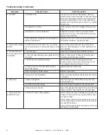
Troubleshooting (continued)

Symptom

Possible Cause

Corrective Action

3. Continued

c. Defective valve.

Turn the valve knob to the ON position. Place the 
ON/OFF switch in the ON position. Check the millivolt 
meter a the thermopile terminals. The millivolt meter 
should read greater than 125mV. If the reading is ac-
ceptable, and if the burner does not come on, replace 
the gas valve.

d. Plugged burner orifi ce.

Check the burner orifi ce for stoppage. Remove stop-
page.

e. Wall switch or wires are defective.

Follow the corrective action in Symptom and Pos-
sible Cause 1.a above. Check the switch and wiring. 
Replace where defective.

f.  High limit switch is defective or has reached its 
maximum temperature.

Allow the unit to cool.  If the burner remains lit after 
the fi replace warms up, the switch is good.

4. Frequent pilot outage 
problem.

a. Pilot fl ame may be too high or too low, or blow-
ing out (high pressure), causing pilot safety to drop 
out.

Clean thermocouple and adjust the pilot fl ame for 
maximum fl ame impingement. Follow lighting instruc-
tions carefully.

5. The pilot and main 
burner extinguish while 
in operation.

a.  No LP in tank.

Check the LP (propane) tank. Refi ll the fuel tank.

b.  Inner vent pipe leaking exhaust gases back into 
the system.

Check venting system for damage. Replace/repair 
improperly assembled pipe sections.

c.  Horizontal vent improperly pitched.

the horizontal vent cap should slope down only 
enough to prevent any water from entering the unit.  
The maximum downward slope is 1/4 inch.

d. Glass too loose and air tight packet leaks in 
corners after usage.

Replace glass panel assembly.

e. Bad thermopile or thermocouple.

Replace if necessary.

f. Improper vent cap installation.

Check for proper installation and freedom from debris 
or blockage.

6. Glass soots.

a. Flame impingement.

Adjust the log set so that the fl ame does not exces-
sively impinge on it.

b. Improper air shutter setting.

Adjust the air shutter located on the control panel.

c. Debris around air shutter.

Inspect the opening at the base of the burner. NO MA-
TERIAL SHOULD BE PLACED IN THIS OPENING.

7.  Flame burns blue 
and lifts off burner.

a. Insuffi cient oxygen being supplied.

Ensure that the vent cap is installed properly and free 
of debris. Ensure that the vent system joints are tight 
and have no leaks.

Ensure that no debris has been placed at the base of, 
or in the area of the air holes in the center of the base 
pan beneath the burner.

Ensure that the glass is tightened properly on the unit, 
particularly on top corners.

Summary of Contents for QV36DC-A

Page 1: ... other flammable materials away DO NOT DISCARD THIS MANUAL CAUTION Important operating and maintenance instruc tions included This appliance may be installed as an OEM installation in manufactured home USA only or mobile home and must be installed in accordance with the manufacturer s instructions and the manufactured home construction and safety standard Title 24 CFR Part 3280 or Standard for Ins...

Page 2: ...W these installation instructions may result in a possible fire hazard and will void the warranty Prior to the first firing of the fireplace READ the Using Your Fireplace section of the Owners Guide DO NOT USE this appliance if any part has been under water Immediately CALL a qualified service technician to inspect the unit and to replace any part of the control system and any gas control which ha...

Page 3: ...A Vent System Approvals 14 B Installing Vent Components 21 C Vent Termination 24 Step 4 Positioning Leveling and Securing the Fireplace 27 Step 5 The Gas Control System 27 Step 6 The Gas Supply Line 28 Step 7 Gas Pressure Requirements 28 Step 8 Wiring the Fireplace 29 Step 9 Finishing 30 Step 10 Installing Trim Logs and Ember Material 31 Installing the Trim 31 Refractory Kit Placement 31 Positioni...

Page 4: ...a Fire QV36DC A 2161 900 Rev B 10 08 4 Service Parts Diagram QV36DC A Service Parts R Beginning Manufacturing Date Apr 2008 Ending Manufacturing Date ______ 6 7 8 9 10 11 12 14 13 Log Set Assembly 3 5 4 2 1 ...

Page 5: ...8 001 9 Andirons Pre Nov 2008 80784 Post Nov 2008 2014 300 10 Base Refractory NG LP 2018 100 11 Surround 2101 260 12 Glass Door Assembly GLA 6TRXI Y 13 Burner 2018 005 Y 14 Junction Box 4021 013 Y Exhaust Restrictor 2027 102 Gasket Assembly 385 402A Includes Vent Seal Cap Burner Neck Shutter Bracket and Valve Plate Gaskets Glass Clips 060 235 25 Y Glass Latch Assembly 386 122A Y Lava Rock Bag 060 ...

Page 6: ...tter Sleeve 2026 130 Y 4 Shutter Bracket Assembly 2026 017 Y 5 Orifice NG 3 1 MM 582 8310 Y Orifice LP 1 8 MM 582 818 Y 6 Flexible Gas Connector 383 302A Y 7 Wire Assembly 049 552A Y 8 Valve NG 230 0710 Y Valve LP 230 0720 Y 9 Valve Bracket 2118 104 10 Flex Ball Valve Assembly 302 320A Y 11 Control Panel 291 125 12 Piezo Ignitor 291 513 Y 13 Pilot Control Knob 571 534 Y 14 Flame Control Knob 571 5...

Page 7: ...led in a bedroom or bed sitting room in the U S A and Canada High Altitude Installations U L Listed gas appliances are tested and approved without requiring changes for elevations from 0 to 2 000 feet in the U S A and in Canada When installing this appliance at an elevation above 2 000 feet it may be necessary to decrease the input rating by changing the existing burner orifice to a smaller size I...

Page 8: ...ating appliance or equipment The sign shall read in print size no less than one half 1 2 in in size GAS VENT DIRECTLY BELOW KEEP CLEAR OF ALL OB STRUCTIONS Inspection The state or local gas inspector of the side wall horizon tally vented gas fueled equipment shall not approve the installation unless upon inspection the inspector ob serves carbon monoxide detectors and signage installed in accordan...

Page 9: ... Fail ure to follow these instructions will void the owner s warranty and may present a fire hazard The Hearth Home Technologies Warranty will be voided by and Hearth Home Technologies disclaims any responsibility for the following actions Installation of any damaged fireplace or vent system component Modification of the fireplace or direct vent system Installation other than as instructed by Hear...

Page 10: ...SS GAS CONTROLS RATING PLATE AND LABELS GAS LINE ACCESS 41 1 8 1044mm 38 965mm 36 1 8 916mm 25 1 4 642mm 34 5 8 879mm 8 5 8 219mm VENT COLLARS ELECTRICAL ACCESS 26 7 8 682mm 12 3 4 323mm 3 1 2 90mm GAS LINE ACCESS 2 1 8 55mm 6 7 8 174mm 14 1 4 362mm 8 5 8 219mm VENT COLLARS 21 1 2 548mm 11 5 8 297mm 28 1 2 724mm ...

Page 11: ...ruction Constructing the Fireplace Chase A chase is a vertical box like structure built to enclose the gas fireplace and or its vent system Vertical vents that run on the outside of a building may be but are not required to be installed inside a chase CAUTION TREATMENT OF FIRESTOP SPACERS AND CONSTRUCTION OF THE CHASE MAY VARY WITH THE TYPE OF BUILDING THESE INSTRUCTIONS ARE NOT SUBSTITUTES FOR TH...

Page 12: ... E D 1 2 CLEARANCE FROM BACK OF FIREPLACE TO COMBUSTIBLE 0 CLEARANCE TO FRAMING MEMBER 0 CLEARANCE 1 2 CLEARANCE FROM BOTH SIDES OF FIREPLACE TO COMBUSTIBLE FRAMING MEMBER WALL STUD 3 1 2 3 A 42 B 38 1 2 C 22 D 42 3 4 E 27 7 8 A B C Fireplace framing can be built before or after the fireplace is set in place Framing should be positioned to accommodate wall coverings and fireplace facing material T...

Page 13: ... Vent Component Specifications 5 inch inner pipe 8 inch outer pipe NOTE PIPES OVERLAP 1 1 4 INCHES AT EACH JOINT DVP90ST 12 9 16 11 1 4 7 1 4 1 1 4 TYP 1 2 TYP 8 9 16 DVP36 DVP48 48 24 36 4 6 DVP4 DVP6 12 DVP12 2 MIN DVP12A 12 3 16 MAX DVP24 9 7 8 45 0 10 1 4 DVP45 14 1 4 ...

Page 14: ...ng collar NOT used Terminations Kits HORIZONTAL TERMINATION WALL FIRESTOP 90 DEGREE ELBOW PIPE LENGTH CEILING FIRESTOP VERTICAL TERMINATION STORM COLLAR ROOF FLASHING DVP TVHW DVP TRAP SERIES DVP TB1 Required to have a minimum of 3 feet of vertical in the vent system Step 3 Installing the Vent System A Vent System Approvals This model is approved to use DVP series direct vent pipe components and t...

Page 15: ... vent ing configurations over 20 feet install the flue re strictor 2027 102 See flue restrictor installation instructions CAP V Figure 7 Figure 8 ADJUSTABLE FLUE RESTRICTORS 2 Adjustable Flue Restrictor see Figure 8 5 4 3 2 1 1 2 3 4 5 CHART Vertical Top Vent NG Top Vent LP Rear Vent NG Rear Vent LP 4 2 2 2 3 No Restrictor No Restrictor 8 3 3 2 3 2 2 No Restrictor 15 3 4 3 4 3 3 2 3 20 4 4 3 4 3 4...

Page 16: ...Kit No H Max Run DVP TRAP 24 610 mm Figure 10 Corner Installation NOTE This model is tested and approved to use 45 elbows in corner installations However 90 elbows will result in better performance Figure 9 Horizontal Installation 90 DEGREE ELBOWS 45 DEGREE ELBOW H ...

Page 17: ... Figure 11 Venting with One 90 Elbow VENTING WITH ONE 1 90 ELBOW VENTING WITH ONE 1 90 ELBOW V FT H FT 1 MIN 305mm 5 MAX 1 52m 2 MIN 610mm 10 MAX 3 1m 3 MIN 914mm 15 MAX 4 65m 4 MIN 1 22m 20 MAX 6 2m V H 40 MAX 12 4MM H 20 MAX 6 2m Figure 12 Venting with One 90 Elbow NOTE If a 90o elbow is first attached to the unit the maximum horizontal run is 3 feet 914mm NOTE For corner installations A 6 inch ...

Page 18: ...X 3 1m 3 MIN 914 mm 6 MAX 1 86 m 15 MAX 4 65m 4 MIN 1 22 m 8 MAX 2 48 m 20 MAX 6 2m V H H1 40 MAX 12 4 m H 8 MAX 2 48 m H H1 20 MAX 6 2m Figure 14 Venting with Two 90 Elbows VENTING WITH TWO 2 90o ELBOWS V FT H H1 FT 1 MIN 305mm 5 MAX 1 52m 2 MIN 610mm 10 MAX 3 1m 3 MIN 914mm 15 MAX 4 65m 4 MIN 1 22m 20 MAX 6 2m V H H1 40 MAX 12 4m H H1 20 MAX 6 2m V V1 H 40 MAX 12 4m H1 V H V V1 H H1 H V ...

Page 19: ...X 3 1m 3 MIN 914mm 6 MAX 1 86m 15 MAX 4 65m 4 MIN 1 22m 8 MAX 2 48m 20 MAX 6 2m V H H1 H2 40 MAX 12 4 m H 8 MAX 2 48 m H H1 H2 20 MAX 6 2 m V H H H1 H2 1 MIN 305mm 2 MAX 610mm 5 MAX 1 52m 2 MIN 610mm 4 MAX 1 22m 10 MAX 3 1m 3 MIN 914mm 6 MAX 1 86m 15 MAX 4 65m 4 MIN 1 22m 8 MAX 2 48m 20 MAX 6 2m V1 V H H1 40 MAX 12 4 m H 8 MAX 2 48 m H H1 20 MAX 6 2 m V H H H1 H V H1 V1 H H1 H2 V ...

Page 20: ...m 10 MAX 3 1m 3 MIN 914mm 15 MAX 4 65m 4 MIN 1 22m 20 MAX 6 2m NOTE H H1 20 MAX 6 2m V V1 H H1 40 MAX 12 4m V FT H H1 FT 1 MIN 305mm 5 MAX 1 52m 2 MIN 610mm 10 MAX 3 1m 3 MIN 914mm 15 MAX 4 65m 4 MIN 1 22m 20 MAX 6 2m H H1 20 MAX 6 2m NOTE V V1 H H1 40 MAX 12 4m Figure 16 Venting with three 90 elbows V H H1 V1 V H H1 V1 ...

Page 21: ...arting Collars To attach the first vent component to the starting collars of the fireplace Make sure that the fiberglass gasket supplied in the manual bag seals between the first 8 inch 203mm vent component and the outer fireplace wrap Using 2 self tapping screws from the manual bag secure that gasket to the outer wrap see Figure 18 Figure 18 Fiberglass Gasket OUTER WRAP FIBERGLASS GASKET FIRST VE...

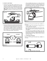
Page 22: ...ositioned so that it creates a 1 2 inch airspace between the shield and the combustible surface See Figure 20 Figure 22 Adding Venting Components Refer to Cinch Pipe and Termination Cap installation in structions Continue adding vent components locking each suc ceeding component into place Ensure that each succeeding vent component is securely fitted and locked into the preceding component in the ...

Page 23: ...nter of the hole is one 1 inch 25 4mm above the center of the horizontal vent pipe Position the firestops on both sides of the hole previously cut and secure the firestops with nails or screws The heat shields of the firestops MUST BE placed to wards the top of the hole Continue the vent run through the firestops Figure 24 Heat Shield Interior Exterior Firestops TRIM HEAT SHIELD IF TOO LONG ADD TO...

Page 24: ...e the ceiling IS an attic position and secure the firestop on top of the previously framed hole NOTE Keep insulation away from the vent pipe at least 1 inch 25mm Figure 27 Attic Firestop JOIST CEILING FIRESTOP CEILING NAILS 4 REQUIRED CEILING CEILING FIRESTOP RAFTER NAILS 4 REQUIRED NOTE There must be NO INSULATION or other combustibles inside the framed firestop opening Figure 25 10 x 10 Hole New...

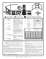
Page 25: ...itted with the dimensions specified for vinyl or non vinyl siding and soffits 1 There must be 3 feet minimum between termination caps 2 All mechanical air intakes within 10 feet of a termination cap must be a minimum of 3 feet below the termination cap 3 All gravity air intakes within 3 feet of a termination cap must be a minimum of 1 foot below the termination cap See Note 1 See Note 2 Note 3 Loc...

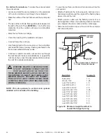
Page 26: ...IN THE INTEREST OF SAFETY SEE FIGURE 30 FOR MINIMUM HEIGHTS PROVIDED THE TERMINA TION CAP IS AT LEAST TWENTY INCHES FROM A VERTICAL WALL AND 2 FEET BELOW A HORI ZONTAL OVERHANG NOTE This also pertains to vertical vent systems installed on the outside of the building Roof Pitch H min ft flat to 6 12 1 0 6 12 to 7 12 1 25 over 7 12 to 8 12 1 5 over 8 12 to 9 12 2 0 over 9 12 to 10 12 2 5 over 10 12 ...

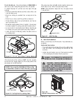
Page 27: ...properly position level and secure the fireplace Figure 31 Proper Positioning Leveling and Securing of a Fireplace Figure 32 Gas Control System STANDING PILOT Step 5 The Gas Control System WARNING THIS UNIT IS NOT FOR USE WITH SOLID FUEL The type of gas control system used with this model is Standing Pilot Ignition Standing Pilot Ignition System This system includes millivolt control valve standin...

Page 28: ...eplace lower grille insert the gas supply line through the gas line hole and connect it to the shut off valve When attaching the pipe support the control so that the lines are not bent or torn After the gas line installation is complete all connections must be tightened and checked for leaks with a com mercially available non corrosive leak check solution Be sure to rinse off all leak check soluti...

Page 29: ... BLK BLK BLK WHT GROUND WHT BLK BLK BLK BLOWER SENSOR SWITCH FAN RECEPTACLE SPEED CONTROL Step 8 Wiring the Fireplace NOTE Electrical wiring must be installed by a licensed electrician CAUTION DISCONNECT REMOTE CONTROLS IF ABSENT FOR EXTENDED TIME PERIODS THIS WILL PREVENT ACCIDENTAL FIREPLACE OPERATION Appliance Requirements This appliance DOES NOT require 110 120 VAC to operate A 110 120 VAC cir...

Page 30: ...HIGH TEMPERATURE 300 F 149 C MIN TOP SIDE SEAL JOINT CAUTION IF JOINTS BETWEEN THE FINISHED WALLS AND THE FIREPLACE SURROUND TOP AND SIDES ARE SEALED A 300 F MINIMUM SEALANT MATERIAL MUST BE USED THESE JOINTS ARE NOT REQUIRED TO BE SEALED ONLY NON COMBUSTIBLE MATERIAL USING 300 F MINIMUM ADHESIVE IF NEEDED CAN BE APPLIED AS FACING TO THE FIREPLACE SUR ROUND SEE FIGURE 39 Hearth Extensions Ahearth ...

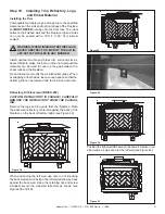
Page 31: ... ING Remove the logs and log grate from the fireplace Place the back wall refractory centered against the back of the fireplace on the back refractory ledge see Figure 38 When positioning the left wall use care in not knocking the back wall down Position the left wall all the way back against the back wall Using the retaining clip and screw included secure the side wall refractory as shown see Fig...

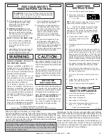
Page 32: ...nit for possible gas leaks Double check vent terminations and front grilles for obstructions Before lighting the fireplace double check the unit for possible obstructions that could be blocking the vent terminations or the front grilles Double check for faulty components Any component that is found to be faulty MUST BE replaced with an approved component Tampering with the fireplace components is ...

Page 33: ...away Do not operate the appliance with panel s removed cracked or broken Replacement of the panel s should be done by a licensed or qualified service person NOT FOR USE WITH SOLID FUEL For use with natural gas and propane A conversion kit as supplied by the manufacturer shall be used to convert this appliance to the alternate fuel Also Certified for Installation in a Bedroom or a Bedsitting Room F...

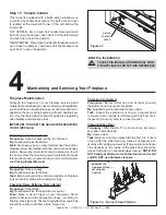
Page 34: ...ake sure the flames are steady not lifting or floating See Figure 44 The thermopile thermocouple tips should be covered with flame See Figure 32 Figure 44 Burner Flame Patterns Checking Vent System Frequency Before initial use and at least annually thereafter more frequently if possible By Qualified service technician Home owner Task Inspect the external vent cap on a regular basis to ensure that ...

Page 35: ...n 15mV replace the thermocouple b Defective valve If the thermocouple is producing more than 15 millivolts replace faulty valve 3 The pilot is burning there is no burner flame the valve knob is in the ON position and the ON OFF switch is in the ON position a ON OFF switch or wires defective Check the ON OFF switch and wires for proper connections Place the jumper wires across the terminals at the ...

Page 36: ...k Check the LP propane tank Refill the fuel tank b Inner vent pipe leaking exhaust gases back into the system Check venting system for damage Replace repair improperly assembled pipe sections c Horizontal vent improperly pitched the horizontal vent cap should slope down only enough to prevent any water from entering the unit The maximum downward slope is 1 4 inch d Glass too loose and air tight pa...

Page 37: ...under this warranty is limited to the purchase price of the product In no event shall HHT be liable for any incidental or consequential damages caused by defects in the product Adjustments regular maintenance cleaning and temporary repairs or the failure to duplicate the problem in the home is not covered under this warranty Page 1 of 2 4021 645A 09 01 08 Warranty Period HHT Manufactured Appliance...

Page 38: ...nd approved by HHT in writing This warranty does not apply to non HHT venting components hearth components or other accessories used in conjunc tion with the installation of this product This warranty is void if the appliance has been over fired or operated in atmospheres contaminated by chlorine fluorine or other damaging chemicals the appliance is subject to prolonged periods of dampness or cond...

Page 39: ......

Reviews: