


Quadra-Fire • QFI30FB-IFT, QFI35FB-IFT Installation Manual • 2555-980 Rev. C • 9/18
6
3
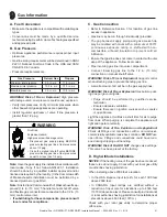
Framing and Clearances
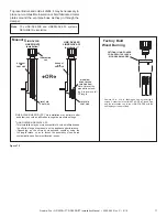
A. Appliance/Decorative Front Dimension Diagram
Dimensions are actual appliance dimensions. Use for reference only. For framing dimensions and clearances refer to Section 4.
Figure 3.1 Appliance Dimensions
*
Dimensions H, O, F and I are measured to the surround brackets.
Note:
Location N on Figure 4.1 is measuring the appliance depth, for installation depth reference Location O. See
also Figure 4.2.
MODEL DIMENSIONS
Location
QFI35FB-IFT
QFI30FB-IFT
Inches Millimeters Inches Millimeters
A
33-13/16
859
29-3/8
746
B
25
635
21
533
C
10-11/16
271
8-11/16
221
D
3-11/16
94
3-11/16
94
E
4-3/8
111
4-1/4
108
F*
14-3/4
375
13-1/4
337
G
6-3/4
172
6-3/4
172
H*
34-5/8
880
30
762
I*
13-3/8
340
11-7/8
302
J
1-7/8
48
1-7/8
48
K
1-5/16
33
1-5/16
33
MODEL DIMENSIONS
Location
QFI35FB-IFT
QFI30FB-IFT
Inches Millimeters Inches Millimeters
L
2-1/8
54
2-1/8
54
M
5-3/4
145
4-1/2
114
N
16-5/8
422
15-1/8
384
O*
17-7/8
454
16-3/8
416
P
24-3/8
619
22-3/8
568
Q
19-7/8
505
17-7/8
454
R
31-3/8
797
26-11/16
678
S
2-5/16
59
2-1/4
57
T
4-1/2
108
4
101
U
21-3/4
552
20
508
U
L
M
T
A
B
C
D
E
F
H
G
I
K
J
P
Q
R
S
O
N
GAS
ACCESS


