27
REAR PANEL
Footswitch jack
Connects to the footswitch cable.
Coax connector
Connects to the converter
DB9 connector
I/O Connector
Electrical line cord
Connects to the 220/240V electrical outlet
Temperature probe jack Connects to the optional temperature probe
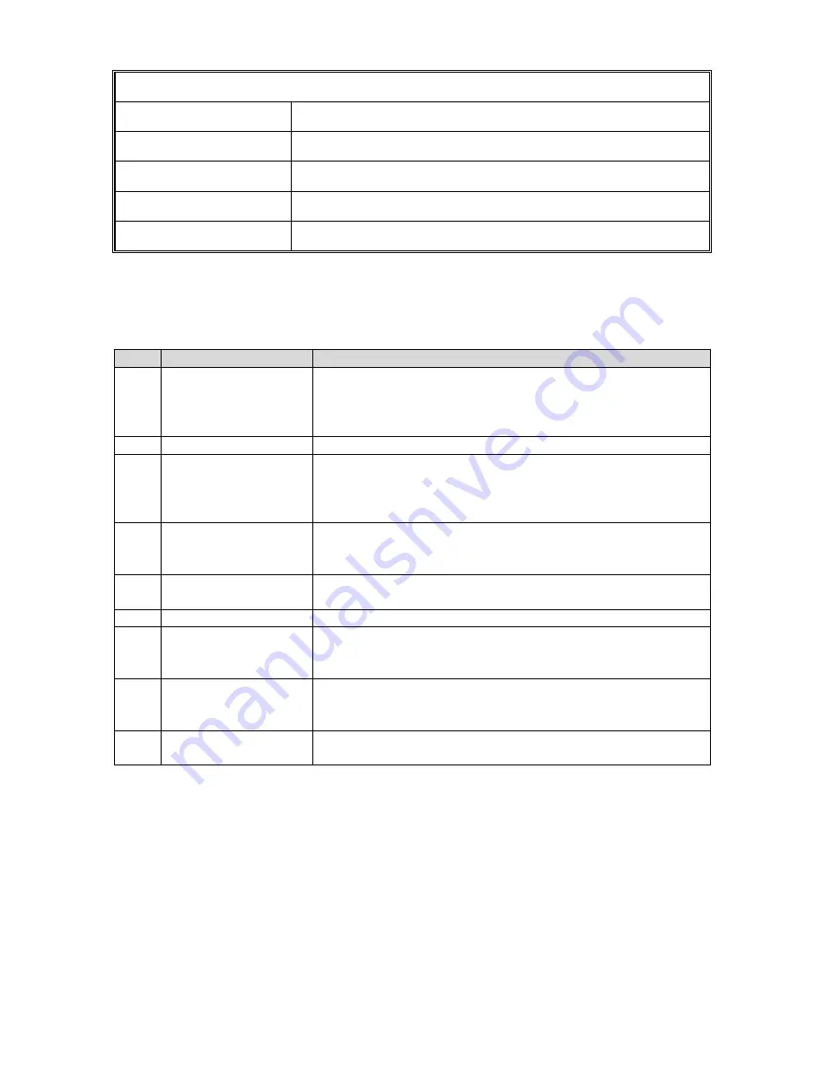
I/O Connector Description
The following I/O connections are available for remote control and monitoring. This I/O interface
provides remote monitoring and signaling to the Power Supply. Remote control can be used to
vary the Amplitude, Command Sonics Start, monitor power output and frequency.
PIN
Name
Description
1
O.L. Indication (*1)
Output - Over Load Indicator. When a power supply
overload has occurred this line will be set low referenced
to pin 9. This is an open collector output. See schematic
for ratings.
2
Not Connected
3
Frequency Lock (*1) Output
–
Frequency Lock Indicator. When the power
supply has achieved frequency lock this line will be set
low referenced to pin 9. This is an open collector output.
See schematic for ratings.
4
Frequency Output /
10
Output
–
Square wave output representing the power
supply frequency divided by 10. See schematic for
ratings. This output is referenced to pin 9.
5
Power Output Watts Output
–
Analog output representing power supply output
wattage. 5.44mV = 1 Watt. See schematic for ratings.
6
Ground
Ground
–
Common reference point for pins 2, 5, 7 and 8.
7
Sonics Start
Input
–
Sonics Start signal. Apply a switch closure to
ground (pin 6). This will start the ultrasonic cycle as
programmed by the keypad. See schematic for ratings.
8
Amplitude Control
Input
–
Analog Input representing the Amplitude setting of
the power supply. 0 to 10 VDC signal representing 20% to
100% amplitude. See Note 1. See schematic for ratings.
9
Common Emitter
Common reference point for pins 1, 3, and 4. See
schematic for ratings.
Note 1. In order to activate remote amplitude control, the Amplitude Select switch on the Back
Panel Interface PCBA must be set in the External position. To set the switch, power off the unit
and disconnect the power cord from the wall socket. Remove the six screws holding the cover to
the chassis. Set the switch to External on the Backplane Interface PCB. Re
-install the cover and
fasten all 6 screws. Re-connect the power cord to the wall socket.
Please contact Qsonica for specific applications assistance related to remote control and
monitoring.
18
Summary of Contents for CT2000
Page 30: ...41 Wiring Diagram 30...


