


6
TD-000437-00-B
c. Open the Q-SYS design that contains the amplifier. Select
File > Save to Core and Run
.
d. The amplifier, Core Processor, and any other Q-SYS peripherals included in the design will automatically update.
5.
NAIN A - DE:
Displays the current gain setting of each channel. Combined channels (bridging or parallel) are are displayed together. The green
background is a bargraphical representation of the gain setting as well.
LAN A / LAN B Screen
(Figure 15)
1.
IP Address
—Use Q-SYS Configurator to edit parameters. LAN A is required and cannot be
turned off.
2.
Netmask
.
3.
Nateway
.
4.
LAN B
— LAN B is not required but if it is used, the network parameters appear here..
Health Screen
1. FAN – Speed in RPM; varies with internal temperature.
2. PSU TEMP; CH A&C Temp; CH B&D Temp – The amplifier monitors three different
temperatures and automatically triggers limiting or shutdown at these thresholds:
• Thermal limiting starts at 69º C
• Thermal shutdown at 80º C
3. VRAIL 1; VRAIL 2 – Indicate the output section rail voltages. These are the normal values:
• VRail 1 = +147 VDC +/- 5V (typical)
• VRail 2 = -147 VDC +/- 5 V (typical)
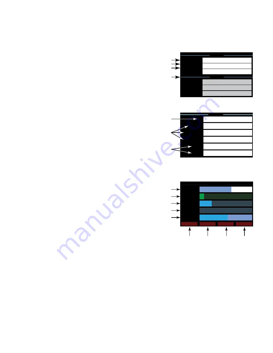
Output Screens
Each output or group of outputs has a dedicated screen.
is an example.
1. GAIN – The gain applied to the signal in the output section. It is controlled by the GAIN
knob on the front panel of the amplifier or the GAIN control in the CXD-Q Output
component in the Q-SYS Design.
2. INPUT – The audio signal level applied to the CXD-Q Output component in the Q-SYS
design. This meter reading can be changed from RMS to Peak in the Amplifier Out
component in the Q-SYS design.
3. VOLTAGE - The output voltage delivered to the loudspeaker. This reading can be RMS or
peak depending on the Meter Select setting in the Q-SYS design for the associated channel.
4. POWER – The power of the amplifier / loudspeaker circuit. This reading can be average
(“RMS”) or peak depending on the Meter Select setting in the Q-SYS design.
5. HEADROOM – The headroom, referenced to the amplifier's maximum output before
clipping.
6. DAC LIMIT – Indicates that the signal to the D to A converter is too high and the limiter has engaged to prevent clipping. This is a sign that the gain
structure is not correct.
7. PROTECT – Indicates that the channel is in Protect Mode. The usual cause is an excessively low load impedance or short circuit.
8. CLIP – Indicates that the output signal exceeds the amplifier's maximum output voltage capability.
9. LIMIT – Indicates the amplifier limiter is acting on the signal. Clipping, excessive output current, short circuits, or excessive operating temperature
will trigger the limiter.
— Figure 15 —
LAN A
1
2
3
4
LAN B
GATEWAY:
0.0.0.0
NETMASK:
255.255.0.0
IP ADDRESS:
192.168.xxx.xxx
GATEWAY:
NETMASK:
IP ADDRESS:
— Figure 16 —
HEALTH
1
FAN:
1109
PSU TEMP:
35.3°C
CH A&C Temp:
35.4°C
2
CH B&D Temp:
35.3°C
VRAIL 1:
149
VRAIL 2:
-151
3
— Figure 17 —
OUTPUT A
1
GAIN:
-23.0 dB
2
Q-LAN INPUT:
-45.0 dB
3
POWER:
.011 W
4
HEADROOM:
-41.3 dB
DAC LIMIT
PROTECT
CLIP
LIMIT
6
7
8
9
VOLTAGE:
.777 V
5