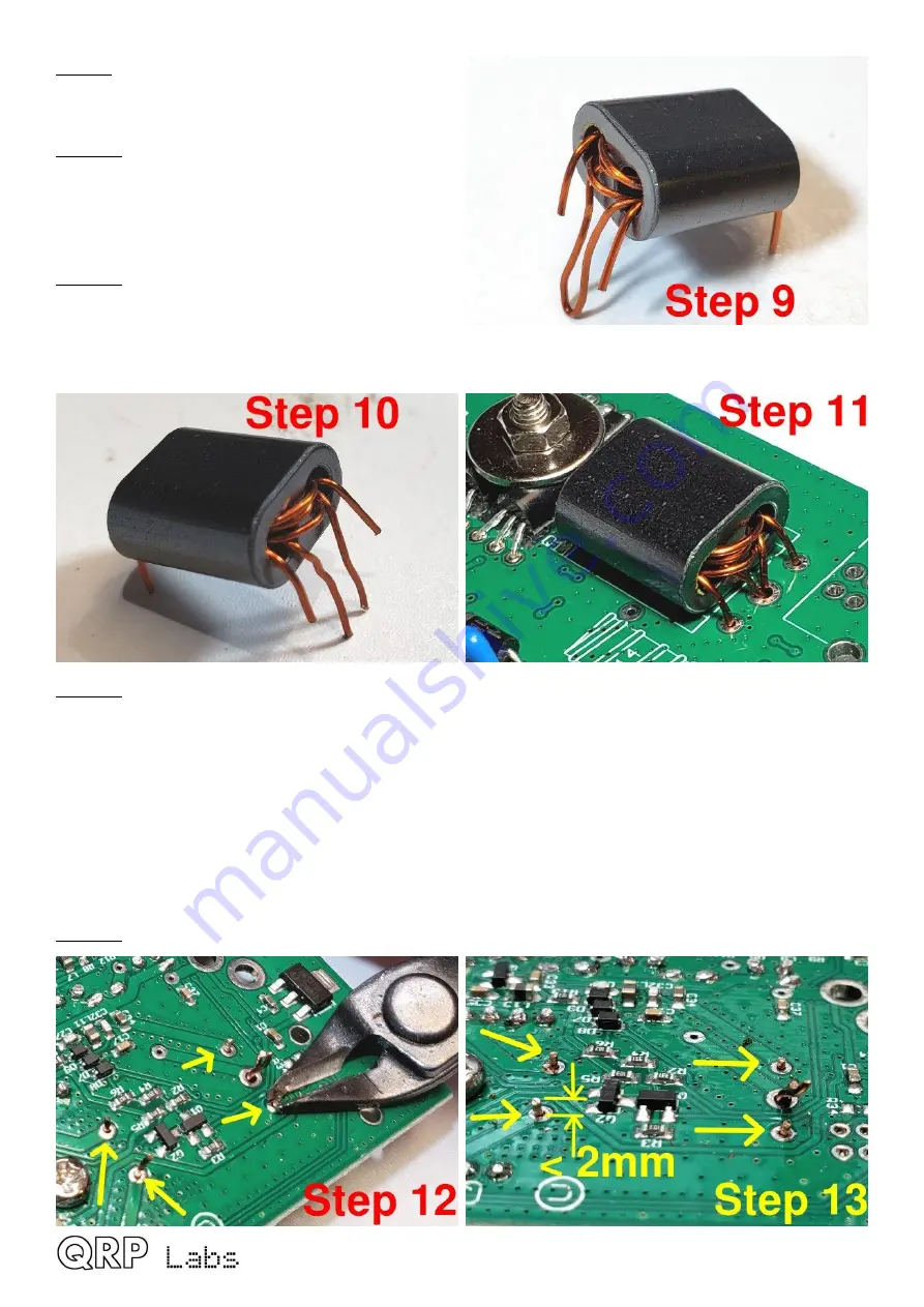
Step 9
: Bend all the wires to point downward in
the position they will need to be, to fit through the
holes in the PCB.
Step 10
: Now cut the center-tap loop; hopefully,
as mine are in this photograph, these two wires
formed by cutting the loop are LONGER than the
two ends of the 3-turn secondary, so that you
cannot mix anything up.
Step 11
: Insert the wires into the holes on the
PCB. The two wires (of the cut loop) that belong
to the center-tap of the 3-turn primary, which are
the longer wires, are inserted into the middle hole
on the right-hand side; this hole is larger than the others and is big enough for both wires to fit in.
Step 12
: Now we need to get the enamel off the wire. Usually on thinner wire, I hold the soldering
iron to the wire until the enamel burns off. But that doesn’t work so well on thicker wire such as
this. So my technique here is to scrape the enamel off, at least partially, using wire cutters. The
correct pressure needs to be applied to the wire cutters, so as NOT to actually cut the wire. I hold
the wire cutter as close to the PCB as possible, then gently but firmly pull the cutter away from the
PCB, scratching off the enamel. Turn the cutter to a different angle and scrape again, 2 or 3 times.
It is not necessary to remove ALL the enamel, if you get a few good scrapes on, enough enamel
will be removed that the soldering iron heat will burn off the rest of the enamel and a good joint will
be achieved. Do this for the 4 winding ends first, leave the two center-tap for later, to make it
easier.
Step 13
: Cut each of the four wire-endings, leaving about 2mm or less, sticking up from the PCB.
QDX assembly Rev 1.00
19
Summary of Contents for QDX
Page 6: ...QDX assembly Rev 1 00 6...
Page 7: ...QDX assembly Rev 1 00 7...
Page 8: ...QDX assembly Rev 1 00 8...


