background image

Software configuration

-15-

Default IP Address: 

192.168.1.254

Default IP subnet mask: 

255.255.255.0

WEB login User Name:

 <empty>

WEB login Password: 

<empty>

3.1

Connect to the WLAN Access Point

This product can be set up using any current web browser, i.e., Internet
Explorer 6 or Netscape Navigator 6.2.3.

Open a WEB browser, i.e. Microsoft Internet Explore, then enter 

192.168.1.254

 on

the URL to connect the WLAN Access Point.

3.2

Prepare your PC to configure the WLAN Access Point

For OS of Microsoft Windows 95/ 98/ Me:
1. Click the Start button and select Settings, then click Control Panel. The Control
Panel window will appear.
Note: Windows Me users may not see the Network control panel. If so, select View
all Control Panel options on the left side of the window
2. Move mouse and double-click the right button on Network icon. The Network
window will appear.
3. Check the installed list of Network Components. If TCP/IP is not installed, click the
Add button to install it; otherwise go to step 6.
4. Select Protocol in the Network Component Type dialog box and click Add button.
5. Select TCP/IP in Microsoft of Select Network Protocol dialog box then click OK
button to install the TCP/IP protocol, it may need the Microsoft Windows CD to
complete the installation. Close and go back to Network dialog box after the TCP/IP
installation.
6. Select TCP/IP and click the properties button on the Network dialog box.
7. Select Specify an IP address and type in values as following example.

·

 IP Address: 192.168.1.1, any IP address within 192.168.1.1 to 192.168.1.253 is
good to connect the Wireless LAN Access Point.

·

 IP Subnet Mask: 255.255.255.0

8. Click OK and reboot your PC after completes the IP parameters setting.

For OS of Microsoft Windows 2000, XP:
1. Click the Start button and select Settings, then click Control Panel. The Control
Panel window will appear.
2. Move mouse and double-click the right button on Network and Dial-up
Connections icon. Move mouse and double-click the Local Area Connection icon.
The Local Area Connection window will appear. Click Properties button in the Local
Area Connection window.
3. Check the installed list of Network Components. If TCP/IP is not installed, click the
Add button to install it; otherwise go to step 6.
4. Select Protocol in the Network Component Type dialog box and click Add button.

Summary of Contents for QP-WO259GHP

Page 1: ...www qpcom com User s Manual QP WO259GHP Outdoor High Power 54Mbps Wireless Access Pointr...

Page 2: ...e WLAN Access Point Chapter IV Management and configuration 16 17 1 Status 18 2 Setup Wizard 19 3 Wireless Basic Settings 21 4 Wireless Advanced Settings 22 5 Wireless Security Setup 24 6 WEP Key Setu...

Page 3: ...hat is Fragment Threshold 46 11 What is RTS Request To Send Threshold 46 12 What is Beacon Interval 47 13 What is Preamble Type 47 14 What is SSID Broadcast 47 15 What is Wi Fi Protected Access WPA 47...

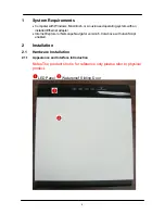
Page 4: ...lledEthernetadapter Internet Explorer or Netscape Navigator version 6 0 or above with JavaScript enabled 2 Installation 2 1 Hardware Installation 2 1 1 Appearance and Interface Introduction Notes The...

Page 5: ...Installation 5 Pass trough Etherne cable from this cable Push these button to remove upper housing Wall Mount Pole Mount...

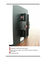
Page 6: ...6 Intergrated 14 dbi dual polarity antenna Pillars to fasten cables to avoid PCB is broken by pulling and draging cables Lan port wih POE...

Page 7: ...Installation 7 WPS Button Reset Button SMA antenna connector...

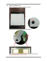
Page 8: ...Step1 push buttons in the sides to remove upper housing Step2 Pull open the click and dismantle the antenna board Step3 Pass through Ethernet cable from the hole insert the cable to LAN port Notes RJ...

Page 9: ...Installation 9 Step4 Installtheantenna Make sure the Antenna is well installed...

Page 10: ...10 Step5 Installtheupperhousing Make sure the housing is well installed...

Page 11: ...Installation 11 Step6 Fasten cables by the black ring Move and fasten cables to the hole with that black ring...

Page 12: ...12 Step7 InstallPOEInjector DC Insertadapter...

Page 13: ...Installation 13 POE this hole is linked to Outdoor AP with RJ 45 LAN this hole is linked to Hub router ADSL modem devies with RJ 45 Step7 Complete diagram...

Page 14: ...gyournetwork youmaychoose to Reset the Access Point to the factory default settings To hard reset the Access Point to Factory Default Settings please do the following Notes Access Point status Power o...

Page 15: ...dd button 5 Select TCP IP in Microsoft of Select Network Protocol dialog box then click OK button to install the TCP IP protocol it may need the Microsoft Windows CD to complete the installation Close...

Page 16: ...e click the right button on Network icon The Network window will appear Click Protocol tab from the Network window 3 Check the installed list of Network Protocol window If TCP IP is not installed clic...

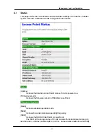
Page 17: ...since WLAN Access Point is powered on Firmwareversion It shows the firmware version of WLAN Access Point Wirelessconfiguration Mode It shows wireless operation mode Band Itshowsthecurrentwirelessopera...

Page 18: ...ess Point gets the IP address The IP address can be set manually to a fixed one or set dynamicallybyDHCPserver IP Address It shows the IP address of WAN interface of WLAN Access Point SubnetMask It sh...

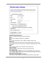
Page 19: ...hannelNumber EnableMacClone SingleEthernetClient 3 Wireless Security Setup This page is used to configure wireless security 4 3 Wireless Basic Settings This page is used to configure the parameters fo...

Page 20: ...uld choose to connect it manually when client mode is enabled SSID It is the wireless network name The SSID can be 32 bytes long Channel Number Select the wireless communication channel from pull down...

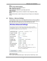
Page 21: ...ration setting Reset Click the Reset button to abort change and recover the previous configuration setting 4 4 Wireless Advanced Settings These settings are only for more technically advanced users wh...

Page 22: ...the wireless data packet transmission Broadcast SSID Click to enable or disable the SSID broadcast function IAPP Click to enable or disable the IAPP function 802 11g Protection Protect 802 11b user RF...

Page 23: ...cation Mode While Encryption is selected to be WPA Click to select the WPA Authentication Mode with Enterprise RADIUS or Personal Pre Shared Key WPA Cipher Suite Enable TKIP or AES Depends on which en...

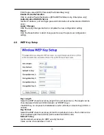
Page 24: ...Reset button to abort change and recover the previous configuration setting 4 6 WEP Key Setup Key Length Select the WEP shared secret key length from pull down menu The length can be chose between 64...

Page 25: ...ting Close Click to close this WEP Key setup window Reset Click the Reset button to abort change and recover the previous configuration setting WEPencryptionkey secretkey length Length Format 64 bit 1...

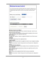
Page 26: ...istered client Apply Changes Click the Apply Changes button to register the client to new configuration setting Reset Click the Reset button to abort change and recover the previous configuration sett...

Page 27: ...ith in the table and then enable the WDS Requirement Set Wireless BasicSettings Mode AP WDS Enable WDS Click the check box to enable wireless distribution system Refer to 4 21 What is Wireless Distrib...

Page 28: ...tatistics Delete Selected Click to delete the selected clients that will be removed from the wireless distribution system Delete All Click to delete all the registered APs from the wireless distributi...

Page 29: ...f sentpackets on the wireless LAN interface Tx Errors It shows the statistic count of error sent packets on the Wireless LAN interface Rx Packets It shows the statistic count of received packets on th...

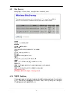
Page 30: ...power level of current AP Select Click to select AP or client you d like to connect Refresh Click the Refresh button to re scan site survey on the screen Connect Click the Connect button to establish...

Page 31: ...nt Range Fill in the start IP address and end IP address to allocate a range of IP addresses client with DHCP function set will be assigned an IP address from the range Show Client Click to open the A...

Page 32: ...o complete the new configuration setting Reset Click the Reset button to abort change and recover the previous configuration setting 4 11 Log This page is used to configure the remote log server and s...

Page 33: ...ts It shows the statistic count of sent packets on the wireless LAN interface Wireless LAN Received Packets It shows the statistic count of received packets on the wireless LAN interface Ethernet LAN...

Page 34: ...the Reset button to abort change and recover the previous configuration setting 4 14 Save Reload Settings This page allows you save current settings to a file or reload the settings from the file tha...

Page 35: ...set the configuration parameter to factory defaults 4 15 Password Setup This page is used to set the account to access the web server of Access Point Empty user name and password will disable the prot...

Page 36: ...ort change and recover the previous configuration setting After set password finish Open a WEB browser i e Microsoft Internet Explore then enter 192 168 1 254 on the URL to connect the WLAN Access Poi...

Page 37: ...N check that the cable for the Ethernet connection is securely inserted Check that the Ethernet adapter is working properly Please see item 3 Check that the drivers for the network adapters are instal...

Page 38: ...rnetintheInfrastructuremode Make sure the wireless client is associated and joined with the correct access point Access Point To check this connection Right click on the Local Area Connection icon in...

Page 39: ...e wireless adapter double click on the Local Area Connection icon in the taskbar select the Support tab and the IP address will be displayed Please refer to Checking the IP Address in the Networking B...

Page 40: ...40 Select the Hardware Tab Click Device Manager...

Page 41: ...ubleshooting 41 Double click on Network Adapters Right click on Realtek RTL8187 Wireless Adapter orwhatevernetwork adapter you are using Select Properties to check that the drivers are installed prope...

Page 42: ...42 Look under Device Status to check that the device is working properly Click OK...

Page 43: ...191 168 1 254 could be an IP address The MAC Media Access Control address is your computer s unique hardware number On an Ethernet LAN it s the same as your Ethernet address When you re connectedtoth...

Page 44: ...ations This configuration is called a Basic Service Set BSS An Extended Service Set ESS is a set of two or more BSSs forming a single subnetwork Since most corporate WLANs require access to the wired...

Page 45: ...additional WLAN Access Points if necessary 6 8 What are the Open System and Shared Key authentications IEEE 802 11 supports two subtypes of network authentication services open system and shared key...

Page 46: ...Youmaywanttotryloweringyourfragmentationthreshold This will cause packets to be broken into smaller fragments These small fragments if corrupted can be resent faster than a larger fragment Fragmentati...

Page 47: ...isn t broadcast for example the D link DWL 120 USB 802 11b adapter Generally if your client hardware supports operation with SSID disabled it s not a bad idea to run that way to enhance network secur...

Page 48: ...s the U S government snext generationcryptographyalgorithm whichwillreplaceDESand 3DES 6 20 What is Inter Access Point Protocol IAPP The IEEE 802 11f Inter Access Point Protocol IAPP supports Access P...

Reviews: