
2
9919-219
Rev. 01292018
3.
For ’63-’72 trucks not originally equipped with a front sway bar remove the bottom rivets in the frame cross member.
See
Figure 1
.
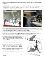
4.
If originally equipped with a front sway bar, remove the rivets from the factory frame mounts.
See Figure 2
.
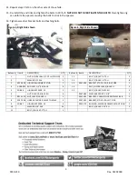
5.
1973 and later trucks not originally equipped with a sway bar will have the holes in the frame already and the QA1 frame
brackets will bolt on using those holes. The factory brackets will need to be replaced with QA1 brackets for trucks
originally equipped with a front sway bar. See
Figure 3
.
6.
Use the supplied hardware to install the QA1 sway bar brackets to the frame and torque to 30 lb.-ft. The 3/8” x 1 ¼”
bolts should be used for the cross member location for ’63-’72 Trucks.
Note:
It is best to install the sway bar mounting
bolts in the brackets before the brackets are installed on the frame. See
Figure 2
.
7.
Grease and install the bushings on the QA1 sway bar and mount to the new frame brackets. Torque to 30 lb.-ft.
8.
Assemble the sway bar end links as shown in
Figure 4
.
Note:
The double ended stud (#8) and rod ends are right hand
thread and thread locker should be applied
only
to the side of the stud without the jam nut.
9.
If the vehicle is using QA1 control arms, attach the sway bar end
links to the control arm using the supplied hardware and
spacers. The wider SG8-67 spacers are used at the control arm
mount. See
Figure 5.
10.
If the vehicle is using stock control arms, attach the end links
to the sway bar. Install the included control arm mount
brackets and lower the vehicle to ride height.
Figure 4
11.
Install the top bolt through the existing bolt hole in the lower
control arm and position the bracket so the end links are
vertical with the truck sitting at ride height. See
Figure 6
.
12.
Mark the remaining hole location on the lower control arm
and move the mounting bracket out of the way.
13.
Using a 3/8” drill bit, drill the hole in the lower control arm and
mount the bracket with the 7/8” long bolt and thin nut in the
vertical position.
Figure 2. ’63-’72 Bracket location
Figure 3. ’73-’91 Bracket location
Figure 4
Figure 5, Right Side Shown