22
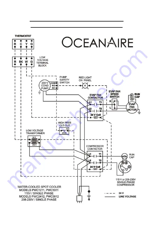
WIRING SCHEMATIC FOR PWC1211,
PWC1811, PWC2412, and PWC3612
07182016
Page 1: ...ENGINEERING INSTALLATION AND SERVICE MANUAL PWC60 PWC12 PWC series Portable Water Cooled Spot Cooler Form EISM PWC 02272017 ...
Page 2: ...ing process of continuous improvement the items and procedures described in this manual are subject to change without notice Please note model and serial num ber of the PWC unit when contacting the factory TABLE OF CONTENTS PAGE GENERAL INFORMATION 1 PRODUCT DATA AND SPECIFICATIONS 2 UNIT DESCRIPTION Standard Features 3 Applications Operation 4 Electrical Configurations 5 Use of Extension Cords 6 ...
Page 3: ...ntained unit with the entire cooling system blower assembly electri cal refrigerant and waterside components neatly arranged in a gray polyester powder coated metal cabinet When connected to the proper source of electrical power a 24 volt thermostat controls the PWC unit to provide the desired level of comfort and cooling A wide variety of accessories and factory installed options are available fo...
Page 4: ...essure dB at 5 feet commercial operation 6 Amps Watts at 208 Volts 208 230 V Models 2 with 85 EWT and 105 LWT 3 CFM with free discharge May COOL down to 55º if equipped with hot gas bypass factory installed COOLING AMBIENT OPERATING RANGE 65º TO 105º WARRANTY ALL OCEANAIRE PRODUCTS ARE COVERED BY THE OCEANAIRE LIMITED WARRANTY PLUS 4 ADDITIONAL YEARS FOR THE COMPRESSOR RESTRICTIONS APPLY 1 YEAR ON...
Page 5: ... handle almost any installation requirement CONDENSATE ALARM LIGHT On the front of all PWC models there is a Condensate Alarm Light RED located near the thermostat The light indicates a condensate pump over flow condition where the pump is either disabled or incapable of removing the condensate water and must be serviced FILTERS All PWC units are equipped with a washable filter at the air intake A...
Page 6: ...d where it is needed Nozzle kits can be used to improve direction of the cooling airflow ROOM AIR CONDITIONER One feature of the PWC is it operates as a room air conditioner because water is used as the means for heat rejection The major advantage of water cooled air conditioning is the convenience of connecting water hoses or lines as compared to the installation of condenser air ducts used for a...
Page 7: ...eliability Refer to the chart below for plug and receptacle details for all PWC models A DAMAGED LCDI POWER SUPPLY CORD MUST BE REPLACED WITH A NEW POWER SUPPLY CORD OBTAINED FROM OCEAN AIRE AND NOT REPAIRED 5 UNIT MODEL PLUG CONFIGURATION RECEPTACLE 115 VOLT PWC1211 PWC1811 NEMA 5 15R 208 230 VOLT SINGLE PHASE PWC2412 PWC3612 NEMA 6 20R 208 230 VOLT SINGLE PHASE PWC6012 NEMA 6 30R 208 230 VOLT 3 ...
Page 8: ...D PROVIDED IT IS RATED AT LEAST 20 AMPS 250 VOLTS 3 PHASE FOR MODEL PWC6032 AN EXTENSION CORD CAN BE USED PROVIDED IT IS RATED AT LEAST 30 AMPS 250 VOLTS 3 PHASE FOR MODELS PWC3634 AND PWC6034 AN EXTENSION CORD CAN BE USED PROVIDED IT IS RATED AT LEAST 20 AMPS 600 VOLTS 3 PHASE SPECIAL NOTICE THREE PHASE OPERATION Models PWC3632 PWC3634 PWC6032 and PWC6034 All three phase models are equipped with ...
Page 9: ...7 PWC ACCESSORIES HOSE KIT NOZZLE KIT DISCHARGE DUCT ADAPTER ROUND FLEX DUCT SOLD SEPARATELY ROUND FLEX DUCT SOLD SEPARATELY EVAPORATOR RETURN AIR PLENUM ...
Page 10: ...d PWC12 2DEP 12 12 Inch Round PWC18 24 DEP 16 16 Inch Round PWC36 60 DISCHARGE DUCT ADAPTER DDA 6 6 Inch Round PWC12 DDA 10 10 Inch Round PWC18 24 2DDA 16 16 inch Round PWC36 PWC60 HOSE KIT HK 1 10FT PWC 12 18 24 HK 2 25FT PWC 12 18 24 HK 5 40FT PWC 12 18 24 HK 3 10FT PWC 36 60 HK 4 25FT PWC 36 60 HK 6 40FT PWC 36 60 PWC ACCESSORIES 8 ...
Page 11: ...diameter nozzles with an approximate compressed length of 15 inches The approximate extended length is 21 inches NK 2 for models PWC18 PWC24 with 2 6 inch diameter nozzles with an approximate compressed length of 22 inches The approximate extended length is 32 inches 2NK 3 for model PWC36 PWC60 with 2 8 inch diameter nozzles with an approximate compressed length of 20 inches The approximate extend...
Page 12: ...or configuration and application information DEP 10 for PWC12 transitions the return air opening to a 10 inch round duct 2DEP 12 for PWC18 and PWC24 transitions the return opening to a 12 inch round duct DEP 16 for PWC36 and PWC60 transitions the return opening to a 16 inch round duct NOTE When a DEP is installed it is recommended to set the evaporator blower speed to high to avoid evaporator coil...
Page 13: ...and PWC24 converts the evaporator discharge to a 10 inch diam eter round duct 2DDA 16 for PWC36 and PWC60 converts the evaporator discharge to a 16 inch diameter round duct When used in conjunction with the evaporator return air plenum DEP the unit can provide closed loop cooling to and from a given space without the influence of any out side air NOTE When a DDA is installed it is recommended to s...
Page 14: ...se kits have FEMALE flare connectors to match the MALE flare fittings on the units see chart below The WATER IN connector consists of a 3 4 hose barb WATER OUT and DRAIN condensate have no fittings and can be fed to a sink or permanent drain When using a hose kit avoid sharp corners hot water pipes and kinking to assure proper water flow of the supply return and drain lines Hose Kit Length Flare C...
Page 15: ...signed for use with up to 350 psig water inlet pressure are available HERESITE TREATED EVAPORATOR COIL For use in chemically corrosive environments the PWC can be manufactured with a Heresite dipped evaporator coil for improved coil life HOT GAS BYPASS VALVE In applications where low evaporator temperatures may occur an optional hot gas bypass valve can be installed to regulate the evaporator temp...
Page 16: ... proper NEMA receptacles refer to Electrical service plug configuration When using extension cords use the proper gauge cord and check cord voltage to the unit TIME DELAY FUSES CIRCUIT BREAKERS ARE RECOMMENDED WARNING OPERATING THE UNIT ON IMPROPER VOLTAGE WILL VOID THE WARRANTY ACCESSORIES Verify that all accessories are correct for the model and are installed in accordance with all instructions ...
Page 17: ... the room temperature After the time delay has been satisfied the fan motor and compressor will start beginning the cooling cycle Remember the set point must be lower than the room temperature for the unit to start AUTO ON COOL OFF TEMPERATURE CHANGE BUTTONS FAN SLIDE SWITCH MODE SLIDE SWITCH TEMPERATURE DISPLAY DIGITAL NON PROGRAMMABLE THERMOSTAT This is a cooling only thermostat Select the tempe...
Page 18: ... rate causing a chattering condition in the water supply line In these cases it is recommended that the water valve be adjusted 1 Disconnect the unit power 2 Remove the unit back panel and locate the water regulating valve in the lower right region of the unit 3 Locate the water valve adjustment screw At the top of the valve there is a square shaped adjustment screw 4 Turn the adjustment screw 1 4...
Page 19: ...Evaporator Blower Evaporator Coil Condensate Pump Control Box Water Valver High Pressure Reset Switch Compressor PWC INTERIOR 17 ...
Page 20: ...sub base Make sure the small thermistor located near the top of the casing for temperature sensing is not bent or damaged 2 To remove the thermostat sub base remove the 2 mounting screws and the 4 wires black red white green Make sure the 4 wires do not fall into the cabinet Install sub base by reversing removal procedure C CONDENSATE ALARM LIGHT To replace the Condensate Alarm Light disconnect th...
Page 21: ...point is too high REMEDY Make sure set point is lower than room temperature You should see a snowflake designating that the thermostat is calling for cooling Note there is a time delay for the compressor CAUSE Thermostat Loose thermostat wires REMEDY Examine the thermostat sub base for loose thermostat wires CAUSE Condensate Alarm REMEDY Check condensate pump and make sure pump is working properly...
Page 22: ...ular basis every six weeks or less depending on the environment The evaporator filter is located behind the return air grille and can be easily removed and cleaned The filter must be washed periodically as needed by placing it in a dishwasher or soaking in a solution of warm water and detergent for 10 minutes Then rinsing clean with hot water and shaking excess moisture from filter DRAINING THE HO...
Page 23: ...IC Water Cooled Spot Cooler SUCTION LINE DISCHARGE LINE FILTER DRIER ACCESS VALVES COMPRESSOR EVAPORATOR BLOWER CONDENSER COIL EVAPORATOR COIL CAPILLARY TUBES HP RESET WATER IN WATER OUT WATER VALVE AIR PIPING SCHEMATIC ...
Page 24: ...22 WIRING SCHEMATIC FOR PWC1211 PWC1811 PWC2412 and PWC3612 07182016 ...
Page 25: ...23 WIRING SCHEMATIC FOR PWC6012 07182016 ...
Page 26: ...art delay has timed out If the thermostat does not power up an electrical condition may need to be addressed Remove the control box cover and observe the LED on the phase monitor The LED signals the following GREEN BLINKING Start delay 120 sec GREEN Proper Operation RED GREEN BLINKING signals reverse phase rotation Switch any two of the power leads for the unit NOT THE MONITOR LEADS and re start R...
Page 27: ...25 WIRING SCHEMATIC FOR PWC3632 ...
Page 28: ...26 WIRING SCHEMATIC FOR PWC6032 ...
Page 29: ...27 WIRING SCHEMATIC FOR PWC3634 and PWC6034 ...
Page 30: ...tten instructions or has been altered or modified in any way b Product that has been subjected to any abnormal power conditions such as loss of power power surges voltage irregularities such as brown outs or phase loss on three phase equipment c any expenses including labor or material incurred during removal or reinstallation of the Product d any workmanship of the installer of the Product This l...
Page 31: ...D For Technical Support or to locate a distributor for service parts contact OceanAire at 847 583 0311 or 1 866 GETAIRE 438 2473 Please indicate the Model Number and Serial Number of the unit to assure proper information and service parts END USER INFORMATION 29 ...
Page 32: ...TECH NOTES Form EISM PWC 02272017 ...