background image

INSTALLATION 

LED POWER SUPPLY - QOM-eLED+DALI-DT8

© 2021 Q-Tran Inc. All rights reserved | 155 Hill St. Milford, CT 06460 | 203-367-8777 | [email protected] | www.q-tran.com 

Specification subject to change. Rev-11-15-22

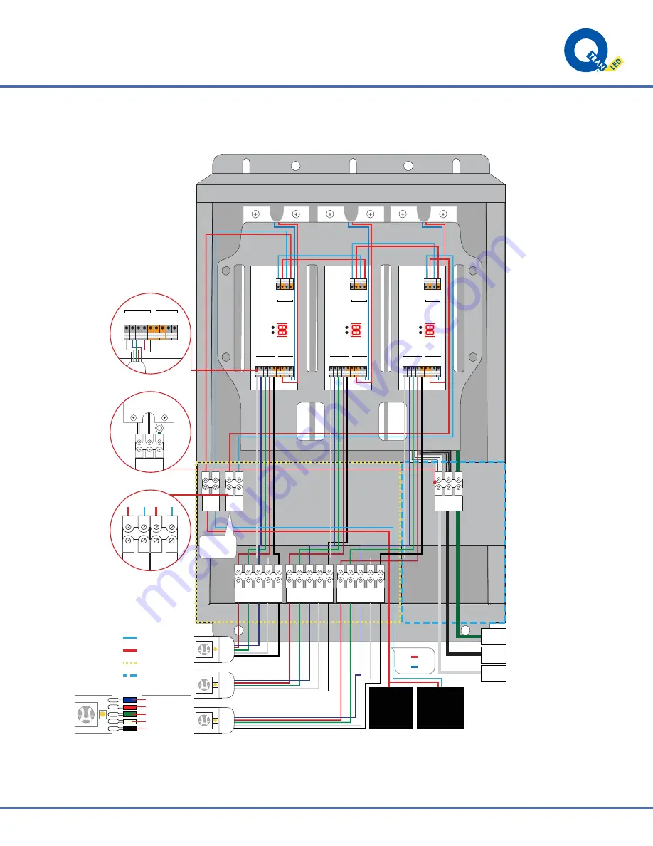
Wiring Installation

C

LED DRIVER 2

  (120 - 277V)

B

LED DRIVER 2

  (120 - 277V)

LED DRIVER 2

B

V-

V-

V+

V+

+

R-

G-

B-

W-

D1+

D2+ D1-

D2-

LED groups

DALI Signal

 in/out

12-36VDC IN

V-

V-

V+

V+

+

R-

G-

B-

W-

D1+

D2+ D1-

D2-

LED groups

DALI Signal

 in/out

12-36VDC IN

V-

V-

V+

V+

+

R-

G-

B-

W-

D1+

D2+ D1-

D2-

LED groups

DALI Signal

 in/out

12-36VDC IN

NEU

GND

HOT

DALI 

IN

DALI 

OUT

SECONDARY

PRIMARY

DA -

DA +

LEAD WIRE

Black = +24V

White = White

Red = Red
Green = Green

Blue = Blue

NEU

GND

HOT

DALI

Controller

*By others.

To next 

power supply

R

G

B

W +24

R

G

B

W +24

R

G

B

W +24

LED

LED

LED

DALI Bus

Power Supply

*By others.

DA +

DA -

Red

Blue

NEU

GND

HOT

LED DRIVER 

(120-277V)

D1+

D1- D2+

D2-

DALI IN

DALI OUT

V-

V-

V+

V+

+

R-

G-

B-

W-

12-36VDC IN

LED groups

LED

D1+

D2+ D1-

D2-

DALI Signal

 in/out

Summary of Contents for QOM-eLED+DALI-DT8

Page 1: ... 7 3 Distances are based on a 5 Voltage drop max This product must be installed in accordance with the applicable installation code by a person familiar with the construction and operation of the product and the hazards involved Technical Information 1 Size Size Max Load Watts Secondary Voltage 12 24VDC Max Prim Amps 120V Max Prim Amps 277V 100W 1x100W 24VDC 0 95A 0 40A 200W 2x100W 24VDC 1 90A 0 8...

Page 2: ...n Lighting Products CSA Std C22 2 No 250 13 14 Light Emitting Diode LED Equipment for Lighting Applications 14 5 15 4 9 22 R G B W 24 R G B W 24 R G B W 24 DALI OUT NEU HOT GND DALI IN LED DRIVER 120V 277V LED DRIVER 120V 277V LED DRIVER 120V 277V BOTTOM TRAY PRIMARY SECONDARY BOTTOM 1 07 1 36 4 90 TOP TRAY 5 Knockouts of 1 07 Hole for 3 4 fitting 4 Knockouts of 1 36 Hole for 1 fitting V V V V R G...

Page 3: ... C22 2 No 250 7 07 CSA C22 2 No 250 0 08 CSA C22 2 No 250 13 14 Input 24VDC Input Voltage Vrms 120 230 277 Input Current max Arms 0 98 0 51 0 43 Inrush Current max Apk 20 Input Frequency Hz 50 60 Input Power W 117 Environmental Min Nom Max THD 20 PF 0 90 Case Temp ºC 90 200us event Efficiency Load 50 Load Efficiency 66 71 76 81 86 91 96 60 70 80 90 100 120 Vac 240 Vac 23 4 23 5 23 6 23 7 23 8 23 9...

Page 4: ...face To DALI Controller V V V V R G B W D1 D2 D1 D2 D1 D2 D1 D2 12 36VDC IN 12 36VDC IN LED groups 2 1 0 2 1 5 mm2 0 35 inch 0 5 1 5 mm2 AWG 20 16 0 35 inch AWG 24 16 VDC and LED connectors Other connectors DALI Signal in out LED V V V V R G B W D1 D2 D1 D2 LED groups 12 36VDC IN V V V V R G B W D1 D2 D1 D2 LED groups 12 36VDC IN DALI Signal in out V V V V R G B W D1 D2 D1 D2 LED groups 12 36VDC I...

Page 5: ... work on a sturdy wooden or fiberglass ladder This power supply must be installed according to the National Electric Code and local codes and ordinances This power supply is to be installed and serviced only by an licensed electricians This power supply is to be installed so that it is not likely to be contacted by people To avoid a hazard to children account for all parts and destroy all packagin...

Page 6: ...Rev 11 15 22 Mounting Options Housing BOTTOM VIEW ISOMETRIC VIEW 1 36 KNOCKOUT 4X FOR 1 FITTINGS 1 07 KNOCKOUT 5X FOR 3 4 FITTINGS 4 90 14 5 15 4 9 22 4 90 NOTE To order additional lengths of wire for connection in the secondary Please call factory for availability QOM must be installed as shown Pole Mount Surface Wall Mount 2 00 0 25 1 4 x2 wood screw or LAG bolt recommened 1 82 3 38 3 14 ...

Page 7: ... default 5 Wire default To DALI Controller V V V V R G B W D1 D2 D1 D2 D1 D2 D1 D2 12 36VDC IN 12 36VDC IN LED groups 2 1 0 2 1 5 mm2 0 35 inch 0 5 1 5 mm2 AWG 20 16 0 35 inch AWG 24 16 VDC and LED connectors Other connectors DALI Signal in out LED V V V V R G B W D1 D2 D1 D2 LED groups 12 36VDC IN V V V V R G B W D1 D2 D1 D2 LED groups 12 36VDC IN DALI Signal in out V V V V R G B W D1 D2 D1 D2 LE...

Page 8: ...ss manually tens ones 0 0 6 3 1 2 Press and hold either button Use the buttons to set address 1 2 Set Address 5 sec 1 Locking the configuration Confirm 1 2 Press and hold either button 5 sec DT8 Dimming Feature NOTE DT8 color type of the dimmer can be TW RGB or RGBW 2 Reset to factory defaults Reset 1 2 1 2 Set Address Press and hold either button 5 sec Use the buttons to set address 2 Set Output ...

Page 9: ...36VDC IN V V V V R G B W D1 D2 D1 D2 LED groups DALI Signal in out 12 36VDC IN V V V V R G B W D1 D2 D1 D2 LED groups DALI Signal in out 12 36VDC IN NEU GND HOT DALI IN DALI OUT SECONDARY PRIMARY DA DA LEAD WIRE Black 24V White White Red Red Green Green Blue Blue NEU GND HOT DALI Controller By others To next power supply R G B W 24 R G B W 24 R G B W 24 LED LED LED DALI Bus Power Supply By others ...

Page 10: ... 4 pi du sol Suitable for use with submersible luminaires or submersible pumps Convient pour une utilisation avec des luminaires submersibles ou des pompes submersibles Suitable for wet locations Convient aux emplacements mouillé CAUTION This control unit has more than one power supply point disconnect all power supplies before servicing ATTENTION Cette unité de contrôle a plus d un point d alimen...

Reviews: