background image

eldoLED POWERdrive 100/S

M

_

+

120-277VAC

50-60Hz

DA

-

+

DA

-

+

~

~

1

2

eldoLED POWERdrive 100/S

M

_

+

120-277VAC

50-60Hz

DA

-

+

DA

-

+

~

~

1

2

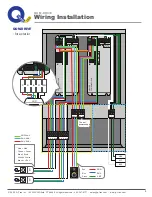
Red = Red
Green = Green
Blue = Blue
White = White
Black = +24V

A

B

DMX Shield
DMX -

PRIMARY
SECONDARY

DMX +

DMX OUT

DMX  IN

_

+

120-277VAC

50-60Hz

DA

-

+

DA

-

+

~ ~

1

2

LED 

R

G

B

W +24V

R G B W+24

A

R G B W+24

B

GND
HOT
NEU

LED 

LED 

NEU

GND

HOT

GND

DMX +
DMX -

Red
Blue
Green

To next 

power supply

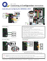
Connecting and configuring the LINEARdrive 100/S

QOM - DRIVE

Connecting & 

Configuration

 Instruction

Primary Wiring

Control Wiring

3

Secondary Wiring

WARNING:

 Risk of electrical shock. May result in serious injury or death. Disconnect power before servicing or installing. 

CAUTION:

 The device may only be connected and installed by a qualified electrician. All applicable regulations, legislation and building codes must be observed. 

                       Incorrect installation of the device can cause irreparable damage to the device and the connected LEDs.  

Commonly Asked Questions

1)

 How can I verify my installation?

 Apply AC input, verify display turns on 

This confirms AC input wiring

 Run “Visual Test Run” : This verifies wiring of LEDs. Make sure LEDs turning on go in 

    same order as the test run

2)

 I don’t have a controller yet, how can I keep my lights on? 

 Change the mode to “COLR” : This allows to manually set a specific color to be on

 Adjust the Hue or WHIT to achieve the desired color : This sets that specific color

3)

 My LEDs aren’t coming out the right color. They look like white has been added in

 Verify the network resolution “NETW RES” : Default is 8 BT

 Check your DMX programming.  Stick controllers come with RGB programs by default. 

    This will cause RGBW LEDs to show pink vs. red

120-277V

AC

50-60Hz

DA

-

+

DA

-

+

~

~

1

2

+

-

+

-

DALI

{

N

L

VAC

120-277

{

12V / 24V DIP switch

24V

12V

Non functional

W

R

B

G

Common anode

R

R

R

R

4 LED groups, 4 control channels

DMX in shield

DMX in 

-

DMX in +

LedSync out 

shield

LedSync out - 

LedSync out +

Ext in 

-

Ext in +


120-277V

AC

50-60Hz

DA

-

+

DA

-

+

~

~

1

2

HOT

GND

NEU

White  = Neutral

Green = Ground

Black  = Hot


120-277V

AC

50-60Hz

DA

-

+

DA

-

+

~

~

1

2

Red = Red
Green = Green
Blue = Blue
White = White
Black = +24V

M

-

+

LED 

R

G

B

W

+24V

LED 


120-277V

AC

50-60Hz

DA

-

+

DA

-

+

~

~

1

2

DMX

DMX in shield

DMX in - 

DMX in +

NOTE:

 The unit will be factory wired based on the way the unit is ordered. 

            Only the one applicable control will be prepared.


:

 DMX shielding wire must be grounded to Earth ground external to power supply.

DMX connections 


M

_

+

120-277V

AC

50-60Hz

DA

-

+

DA

-

+

~

~

1

2

DALI

+

_

+

_

DALI connections 

© 2020, Q-Tran Inc.  155 Hill St. Milford, CT 06460. All rights reserved - 203-367-8777  -  [email protected]  -  www.q-tran.com

Summary of Contents for QOM-DRIVE Series

Page 1: ...ced only by an licensed electricians This power supply is to be installed so that it is not likely to be contacted by people To avoid a hazard to children account for all parts and destroy all packaging materials Risk of Fire Electric Shock Transformer should be installed by a Licensed electrician in accordance with the N E C and all local codes in force INSTALLATION INSTRUCTIONS Must be installed...

Page 2: ...ble to the DMX in DMX in and DMX in shield connector respectively For LedSync out connect the network cable s DMX DMX and DMX shielding wire to the LedSync out LedSync out and LedSync shield connector respectively DMX shielding wire must be grounded to Earth ground external to power supply FEATURES DMX or DALI controllable Surface mount capable Suitable for dry damp and wet locations Suitable for ...

Page 3: ...R 3 4 FITTINGS 4 90 NOTE To order additional lengths of wire for connection in the secondary please call factory for availability QOM must be installed as shown Pole Mount Surface Wall Mount 2 00 0 25 1 4 x2 wood screw or LAG bolt recommened 1 82 3 38 3 14 2020 Q Tran Inc 155 Hill St Milford CT 06460 All rights reserved 203 367 8777 sales q tran com www q tran com ...

Page 4: ... don t have a controller yet how can I keep my lights on Change the mode to COLR This allows to manually set a specific color to be on Adjust the Hue or WHIT to achieve the desired color This sets that specific color 3 My LEDs aren t coming out the right color They look like white has been added in Verify the network resolution NETW RES Default is 8 BT Check your DMX programming Stick controllers ...

Page 5: ... sec W 1 sec RGBW 1 sec display off M LOCK M Lock driver 5 sec NO SOFT HARD M display off RE SET Reset M 5 sec Press menu PRES MENU The colour menu depends on the LED group settings you have selected in step 2 3 Standalone operation Colour or 00 20 display off display off display off SHOW M M M 99 99 0 255 Intensity Speed Show SPD INT M Standalone operation Show or M M 1 512 Network resolution DMX...

Page 6: ...A DA 1 2 Red Red Green Green Blue Blue White White Black 24V M _ 120 277VAC 50 60Hz DA DA 1 2 LED R G B W 24V R G B W 24 A R G B W 24 B DMX OUT DMX IN GND HOT NEU NEU GND HOT A B LED LED GND DMX DMX Red Blue Green To next power supply for exterior QOM DRIVE 2020 Q Tran Inc 155 Hill St Milford CT 06460 All rights reserved 203 367 8777 sales q tran com www q tran com ...

Page 7: ...e VDC Nominal Output Wattage W Input Current A QOM DRIVE 100 QOM DRIVE 200 QOM DRIVE 120 120 1 05 2 10 50 60 50 60 24 24 QOM DRIVE 60 QOM DRIVE 120 120 120 0 67 1 30 50 60 50 60 12 12 100 200 60 120 4 7UDQ QF Q TRAN INC MILFORD CT U S A 203 367 8777 WWW Q TRAN COM 66 3425 15 3425 95 3402 15 3402 95 120V INPUT VOLTAGE OUTPUT VOLTAGE DMX 24V 12V DALI CONTROL TYPE LOW VOLTAGE LIGHTING SYSTEM LED LAND...

Reviews: