6
7
Unlike conventional security cameras,
PTZ cameras require an address and a
connection speed to be set in order for
them to properly operate. The default
settings for this camera are an address of
“1” and a baud rate of 2400 and using the
Pelco-D protocol. However, if your camera
came as part of a bundle, its address may
have been set to something other than “1”.
Check the
Quick Install Poster
that came with
your bundle for specific details. If you are
connecting the camera in accordance to the
instructions included with the bundle, you
should not have to change any of its settings.
In either case, if you are only using a single
PTZ camera you generally do not have to
make any changes and you may proceed to
the next section. Please consult your DVR’s
manual for required settings.
SETTING BAUD RATE AND ADDRESS
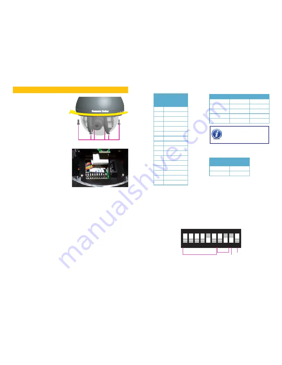
Remove Screws (x6)
Remove Collar
Remove Collar
If you need to change your camera’s settings, they are made using a DIP (dual in-line package)
switch panel located within the camera itself. In general, it is easier to do this before connecting
the camera, but in some cases, you may need to change settings while the camera is
connected to the DVR. In this case, please make a temporary connection by following the
procedures laid out in the next section,
Connecting the Camera
. Please be advised that
adjusting these settings after the camera is mounted can be difficult due to the panel potentially
being inaccessible because of location, position, etc.
To access the panel, one must remove the clear dome by first twisting the metal collar around
the dome counterclockwise and then removing the six screws securing the plastic dome to
the camera. Take care to not scratch the clear dome while removing it. The circuit board on
which the DIP switches are mounted is visible below the camera in the bottom picture.
DIP switches are binary - meaning that they are either On (“1”) or Off (“0”). Different
combinations of ones and zeroes on the board produce different settings. On the QD6531Z,
there are a total of 10 DIP switches but only the first nine have any effect. The first six are for
setting the address of the camera while positions 7 and 8 control the baud rate - which is
the speed in bits per second at which the DVR communicates with the camera for control.
Position 9 is used to set which communications protocol the camera will use - either Pelco-D
or Pelco-D.
Your camera is set to a baud rate of 2400. This will allow you to effectively control the camera
up to 3,000 feet away. Areas with electronic interference may require heavier or shielded
cabling. The higher the setting (may be required by some DVRs), the shorter the control
distance.
ON
1 2 3 4 5 6 7 8 9 10
Camera Address
Baud
Rate
N/A
Comm
Protocol
SETTING BAUD RATE
Baud Rate
Switch Number (BIT)
7
8
1200bps
1
1
2400bps
0
1
4800bps
1
0
9600bps
0
0
SETTING PROTOCOL
Protocol
Switch
Number 9
Pelco-D
1
Pelco-P
0
SETTING CAMERA
ADDRESS
NOTE!
Some DVRs may require specific
connection speeds. Check your system’s
manual for the proper settings.
Address Switch
(8 digits)
Code 1 2 3 4 5 6
1
1 0 0 0 0 0
2
0 1 0 0 0 0
3
1 1 0 0 0 0
4
0 0 1 0 0 0
5
1 0 1 0 0 0
6
0 1 1 0 0 0
7
1 1 1 0 0 0
8
0 0 0 1 0 0
9
1 0 0 1 0 0
10
0 1 0 1 0 0
11
1 1 0 1 0 0
12
0 0 1 1 0 0
13
1 0 1 1 0 0
14
0 1 1 1 0 0
15
1 1 1 1 0 0
16
0 0 0 0 1 0
Address
EXAMPLE
The illustration below shows the settings for a camera with:
n
An address Channel 16
n
A baud rate of 2400
n
Using the Pelco-D communication protocol.


